ENGLISH
I.Vise Level
J.Wheel
K.Guard
L.Spindle Lock
M.Depth Stop Bolt and Jam Nut
N.Trigger Switch
O.Padlock Hole
P.Fence Bolts
X. Lock Pin
Power supply
Be sure your power supply agrees with the nameplate marking. A voltage decrease of more than 10% will cause a loss of power and overheating.
Cutting capacity
The wide vise opening and high pivot point provide cutting capacity for many large pieces. Use the cutting capacity chart to determine total maximum size of cuts that can be made with a new wheel.
Caution: Certain large, circular or irregularly shaped objects may require additional holding means if they cannot be held securely in vise.
Caution: do not cut magnesium with this tool.
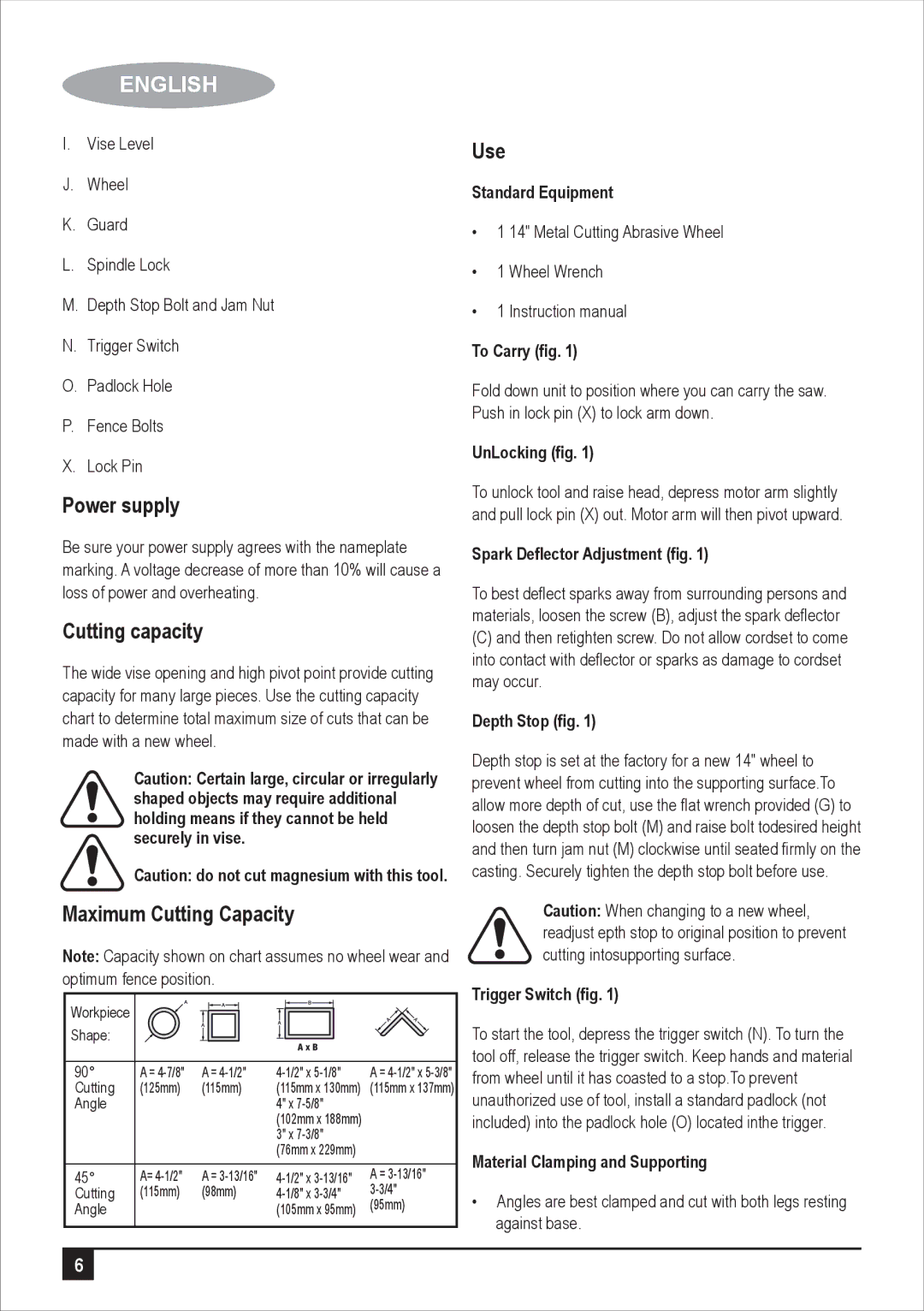
Maximum Cutting Capacity
Note: Capacity shown on chart assumes no wheel wear and optimum fence position.
Workpiece |
|
|
|
|
|
|
|
|
|
|
|
|
|
|
Shape: |
|
|
|
|
|
|
|
|
|
|
|
|
|
|
|
|
|
|
|
|
|
|
|
| A x B |
| |||
|
|
|
|
| ||||||||||
90° | A = | A = | A = | |||||||||||
Cutting | (125mm) | (115mm) | (115mm x 130mm) | (115mm x 137mm) | ||||||||||
Angle |
|
|
|
|
|
|
| 4" x |
| |||||
|
|
|
|
|
|
|
| (102mm x 188mm) |
| |||||
|
|
|
|
|
|
|
| 3" x |
| |||||
|
|
|
|
|
|
|
| (76mm x 229mm) |
| |||||
45° | A= | A = | A = | |||||||||||
Cutting | (115mm) | (98mm) | ||||||||||||
Angle |
|
|
|
|
|
|
| (105mm x 95mm) | (95mm) | |||||
|
|
|
|
|
|
|
|
|
|
|
|
|
|
|
Use
Standard Equipment
•1 14" Metal Cutting Abrasive Wheel
•1 Wheel Wrench
•1 Instruction manual
To Carry (fig. 1)
Fold down unit to position where you can carry the saw. Push in lock pin (X) to lock arm down.
UnLocking (fig. 1)
To unlock tool and raise head, depress motor arm slightly and pull lock pin (X) out. Motor arm will then pivot upward.
Spark Deflector Adjustment (fig. 1)
To best deflect sparks away from surrounding persons and materials, loosen the screw (B), adjust the spark deflector
(C)and then retighten screw. Do not allow cordset to come into contact with deflector or sparks as damage to cordset may occur.
Depth Stop (fig. 1)
Depth stop is set at the factory for a new 14" wheel to prevent wheel from cutting into the supporting surface.To allow more depth of cut, use the flat wrench provided (G) to loosen the depth stop bolt (M) and raise bolt todesired height and then turn jam nut (M) clockwise until seated firmly on the casting. Securely tighten the depth stop bolt before use.
Caution: When changing to a new wheel, readjust epth stop to original position to prevent cutting intosupporting surface.
Trigger Switch (fig. 1)
To start the tool, depress the trigger switch (N). To turn the tool off, release the trigger switch. Keep hands and material from wheel until it has coasted to a stop.To prevent unauthorized use of tool, install a standard padlock (not included) into the padlock hole (O) located inthe trigger.
Material Clamping and Supporting
•Angles are best clamped and cut with both legs resting against base.
6