
GH710 specifications
The Black & Decker GH710 is a versatile and powerful string trimmer designed for homeowners and DIY enthusiasts seeking an efficient solution for maintaining their lawns and gardens. This tool combines modern technology with user-friendly features, making it an essential addition to your yard care arsenal.One of the standout features of the GH710 is its 6.5-amp motor, which provides ample power to tackle thick grass and tough weeds efficiently. The motor is designed to deliver consistent performance, ensuring that users can complete their trimming tasks quickly without compromising on quality or precision. The high torque of the motor allows for effective cutting, making it suitable for various yard conditions.
The GH710 also boasts a 14-inch cutting width, allowing you to cover more ground with each pass. This feature not only saves time but also enhances maneuverability, allowing you to navigate around flower beds, fences, and other obstacles with ease. The trimmer’s lightweight design further contributes to its user-friendliness, reducing user fatigue during extended use.
The unit features an automatic feed spool system which ensures that the cutting line is continuously fed as needed. This eliminates the hassle of manually adjusting or replacing the line frequently, allowing you to focus on your trimming tasks without interruptions. The dual line operation enhances efficiency and provides a cleaner cut, making it suitable for various trimming applications.
Comfort is a paramount concern when it comes to gardening tools, and the GH710 addresses this with its adjustable handle. The handle can be modified to fit the user’s height, providing a more comfortable grip and reducing strain on the wrists during prolonged use. Additionally, the lightweight construction ensures that the trimmer is easy to handle and maneuver.
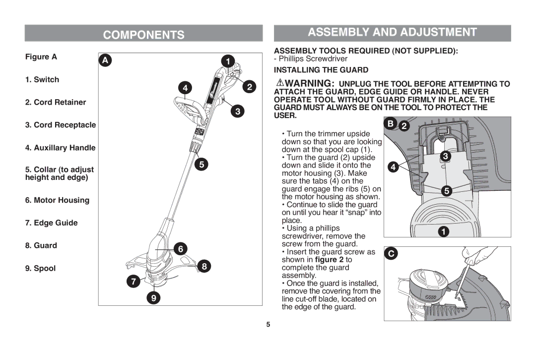
Safety features have also been integrated into the design of the GH710. The safety guard protects the user from debris while operating the trimmer, offering peace of mind as you work on your lawn.
In conclusion, the Black & Decker GH710 string trimmer is a reliable and efficient tool suitable for a variety of yard maintenance tasks. With features like a powerful motor, generous cutting width, automatic feed spool, and user-friendly design, it stands out as an excellent choice for anyone looking to maintain their outdoor spaces effectively. Whether you're trimming edges or tackling overgrown areas, this trimmer delivers the performance needed to achieve a well-groomed lawn.