Extension Handle Kit
INSTRUCTION MANUAL
To be used with units:
Pour utilisation avec les modèles : Para utilizarlo con las siguientes unidades:
GS500, DS600, SSC1000
GS700, DS700
Catalog No. GSH1000
BEFORE RETURNING THIS PRODUCT
FOR ANY REASON PLEASE CALL
1-800-54-HOW-TO (544-6986)
IF YOU SHOULD EXPERIENCE APROBLEM
WITH YOUR BLACK & DECKER PRODUCT,
CALL 1-800-54-HOW-TO (544-6986)
BEFORE YOU CALL, HAVE THE FOLLOWING INFORMATION AVAILABLE, CATALOG No., TYPE No., AND DATE CODE (e.g. 20000130M). IN MOST CASES, ABLACK & DECKER REPRESENTATIVE CAN RESOLVE
YOUR PROBLEM OVER THE PHONE. IF YOU HAVE ASUGGESTION OR COMMENT, GIVE US ACALL.
YOUR FEEDBACK IS VITALTO BLACK & DECKER.
SAVE THIS MANUAL FOR FUTURE REFERENCE.
VEA EL ESPAÑOL EN LA CONTRAPORTADA.
INSTRUCTIVO DE OPERACIÓN, CENTROS DE SERVICIO Y PÓLIZA DE GARANTÍA. ADVERTENCIA: LÉASE ESTE INSTRUCTIVO ANTES DE USAR EL PRODUCTO.
Cat No. GSH1000 | Form # 90500043 | (Sept. ’05) |
Copyright © 2005 Black & Decker | | Printed in China |
 WARNING: Read and understand all instructions. Failure to follow all instructions listed below may result in electric shock, fire and/or serious personal injury.
Important Safety Warnings and Instructions
TO REDUCE RISK OF INJURY:
•Before any use, be sure everyone using this garden appliance reads and understands all safety instructions and other information contained in this manual.
•Save these instructions and review frequently prior to use and in instructing others.
 WARNING: When using gardening appliances, basic safety precautions should always be followed to reduce risk of fire, electric shock, and personal injury, including the following.
•For your own safety before using this accessory with the GS500, DS600, DS700 and the GS700 or the SSC1000 combo unit, read the particular manual for operation of the units and read all the safety sections of the instruction manuals.
For GS500 & DS600
Pour le modèle GS500, DS600
Para GS500, DS600
Figure 1
Figure 2
A  B
B
Figure 3
For DS700, GS700 & SSC1000
Pour les modèles DS700, GS700 et SSC1000
Para DS700, GS700 y SSC1000
Figure 4
Figure 5A
A  B
B
| Figure 8 | Figure 9 |
| A |
| A |
| | B |
| | D |
| | B |
| | C |
| | Figure 10 |
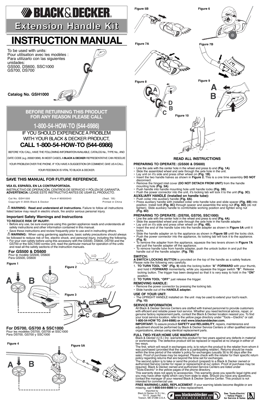
READ ALL INSTRUCTIONS
PREPARING TO OPERATE: (GS500 & DS600)
•Line the axle with the center hole in the wheel and press to end (Fig. 1A).
•Slide the assembled wheel and axle through the axle hole in the unit.
•Lay unit on it’s side and press other wheel on (Fig. 1B).
•Insert the two handle halves as shown in Figure 2. This is a one time assembly DO NOT disconnect.
•Remove the hinged inlet cover (DO NOT DETACH FROM UNIT) from the handle mounting hole (Fig. 3A).
•Push handle into handle mounting hole until handle locks (Fig. 3B).
•Push the power connector into the unit, it’s locking tab will lock it to the unit (Fig. 3C).
AUXILIARY HANDLE (Installed on handle tube):
•Push collar into auxiliary handle (Fig. 8A).
•Press auxiliary handle with installed collar onto handle tube and slide spacer (Fig. 8B) into position. Install bolt (Fig. 8C) through spacer and assemble the wing nut (Fig. 8D) (do not tighten). Slide auxiliary handle to comfortable working position and tighten wing nut
(Fig. 8D)
PREPARING TO OPERATE: (DS700, GS700, SSC1000)
•Line the axle with the center hole in the wheel and press to end (Fig. 4A).
•Slide the assembled wheel and axle through the axle hole in the handle adapter.
•Lay unit on it’s side and press other wheel on (Fig. 4B).
•Insert the end of the handle tube into the handle adapter as shown in Figure 5A until it locks.
•Slide the handle adapter on to the appliance as shown in Figure 5B until the locks click.
•Push the power connector into the appliance, its locking tab will lock it to the appliance.
(Fig. 6)
•To remove the adapter from the appliance, squeeze the two levers shown in Figure 7A and pull the handle adapter off the appliance.
•To remove handle tube from handle adapter, push the unlock button in and pull the handle out of the handle adapter. (Fig. 7B)
SWITCH:
A SWITCH LOCKING BUTTON is provided on the top of the handle as a safety feature. Please note the following very carefully.
1.TO TURN TOOL “ON” (Fig. 9) slide the locking button “A” FORWARD with your thumb, and hold it FORWARD momentarily, while you squeeze the trigger switch “B”. Release locking button. The trigger has been designed so that it is very easy to hold in the “ON” position.
2.TO TURN TOOL “OFF” just release the trigger.
REMOVING HANDLE:
•Remove the power connector by pressing the locking tab.
•Slide handle out of the HANDLE adapter.
USE OF YOUR UNIT:
•The UPRIGHT HANDLE installed on the unit may be used to extend your tool’s reach.
(Fig. 10)
SERVICE INFORMATION
All Black & Decker Service Centers are staffed with trained personnel to provide customers with efficient and reliable power tool service. Whether you need technical advice, repair, or genuine factory replacement parts, contact the Black & Decker location nearest you. To find your local service location, refer to the yellow page directory under "Tools—Electric" or call:
1-800-54-HOW TO. (544-6986) or visit www.blackanddecker.com.
IMPORTANT: To assure product SAFETY and RELIABILITY, repairs, maintenance and adjustment should be performed by Black & Decker Service Centers or other qualified service organizations, always using identical replacement parts.
FULL TWO-YEAR HOME USE WARRANTY
Black & Decker (U.S.) Inc. warrants this product for two years against any defects in material or workmanship. The defective product will be replaced or repaired at no charge in either of two ways.
The first, which will result in exchanges only, is to return the product to the retailer from whom it was purchased (provided that the store is a participating retailer). Returns should be made within the time period of the retailer’s policy for exchanges (usually 30 to 90 days after the sale). Proof of purchase may be required. Please check with the retailer for their specific return policy regarding returns that are beyond the time set for exchanges.
The second option is to take or send the product (prepaid) to a Black & Decker owned or authorized Service Center for repair or replacement at our option. Proof of purchase may be required. Black & Decker owned and authorized Service Centers are listed under "Tools-Electric" in the yellow pages of the phone directory.
This warranty does not apply to accessories. This warranty gives you specific legal rights and you may have other rights which vary from state to state. Should you have any questions, contact the manager of your nearest Black & Decker Service Center. This product is not intended for commercial use.
FREE WARNING LABEL REPLACEMENT: If your warning labels become illegible or are missing, call 1-800-544-6986for a free replacement.
Imported by | | |
Black & Decker (U.S.) Inc., | | See ‘Tools-Electric’ |
701 | E. Joppa Rd. | | – Yellow Pages – |
Towson, | MD 21286 U.S.A. | | for Service & Sales |