4 x 1 DVI and Audio Switches
©Copyright 2013. Black Box Corporation. All rights reserved. Black Box® and the Double Diamond logo are registered trademarks of BB Technologies, Inc. Any
FREE! Live, 24/7 Tech Support is just 30 seconds away.
Chapter 4: Operation/Chapter 5: IR Remote Control
4. Operation
LED Indicator
The Power LED turns green when the video switch is powered on. When a video port is selected, its corresponding Port LED turns yellow.
Push Button
Press the corresponding button to select a port.
Function button
The Function button adjust the optimal video strength corresponding to the length and quality of DVI cable.
To adjust the video signal strength, follow these steps:
1.Press the Function button three times.
2.Press Push button #1 one or two times to adjust the selected port’s input video strength. One beep = Normal or two beeps = Enhance.
or
Press Push button #3 one or two times to adjust the selected port’s output current. One beep = Normal or two beeps = Enhance.
or
Press Push button #4 one, two, or three times to adjust the selected port’s output emphasis. One beep = no
3.Once the setting is finished, press the Function button one time to exit the setting.
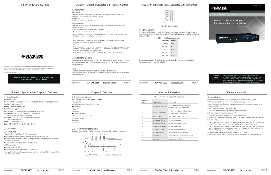
5. IR Remote Control
The remote control operates within a
NOTES:
1.Remove the battery protector on the remote control before operation.
2.On the remote control, only buttons
Page 5 |
Chapter 5: IR Remote Control/Chapter 6: Serial Control
1 | 2 | 3 | 4 |
5 | 6 | 7 | 8 |
9 | 10 | 11 | 12 |
13 | 14 | 15 | 16 |
SHIFT |
| VIDEO | AUDIO |
|
| ON/OFF | ON/OFF |
| RESOURCES |
|
|
13 | 14 | 15 | 16 |
Figure 5-1. Remote control.
6. Serial Control
The DVI and audio switches’ built in serial interface enables users to control the switch via a PC, serial controller devices, or home theater system. The controller’s serial port should be configured as shown in Table
Table
Parameter | Setting |
|
|
Baud Rate | 9600 |
|
|
Data Bits | 8 |
|
|
Parity | None |
|
|
Stop Bits | 1 |
|
|
Flow Control | None |
|
|
To select a source device via serial interface, select the number that corresponds to the port. For example, send “1” to switch to Port 1.
Page 6 |
4 x 1 DVI and Audio Switch
Send up to four source inputs for screen output to one display.
Customer Order
Support call
Information week: Call
Chapter 1: Specifications/Chapter 2: Overview
1. Specifications
Enclosure — Metal
Maximum Video Resolution — Full HD 1080p (1920 x 1080), WUXGA (1920 x 1200)
Number of DVI Inputs — (4)
Remote Control Support — Yes
Serial Control Support
User Controls — (1) Function button, (4) port selection buttons
Connectors — Input: (4) DVI (digital only), (4) audio jacks;
Output: (1) DVI (digital only), (1) audio jack
Indicators — (5) LEDs: (1)
(4)LEDs for video input Power — Consumption: 4.5 W
Size — 1.3"H x 8.7"W x 3.9"D (3.4 x 22 x 10 cm)
2.Overview
2.1 Features
•Select (1) DVI + Audio from (4) DVI + Audio sources.
•Control via
•Function button adjusts the optimal video signal strength corresponding to the length or quality of DVI cable.
•LED shows the active status of DVI + Audio sources.
•HDTV compatible.
•Protects content via HDCP.
•Supports up to Full HD 1080p/1920 x 1200 resolution.
•Compatible with most of the popular screen resolutions to XGA, SXGA, UXGA, WSXGA, Full HD, WUXGA system.
Chapter 2: Overview
2.2 What’s Included
4x 1 DVI and Audio Switch
• Video switch
• (1) DB9 F to ear jack cable,
• Rear bracket
• Screw kit
• Foot pad
• IR remote controller
• Power supply and power cord
• This user manual
Optional:
• Audio cable
2.3 Hardware Description
Figure 2-1 shows the front and back panels of the AVSW-DVI4X1. Table 2-1 describes its components.
| 1 | 3 | 1 | 3 | 1 3 | 1 3 |
|
|
|
|
|
|
|
|
| 4 X 1 D V I S w i t c h w i t h A u i d o | |
4 |
|
|
|
|
|
|
| 2 |
| 1 |
| 2 | 3 | 4 |
|
| |
8 |
|
|
|
|
|
|
|
|
|
|
|
|
|
|
|
| 5 |
|
| OUTPUT |
|
| 4 | 3 | 2 | 1 |
10 | 9 | 6 |
|
|
|
| 7 |
|
Figure 2-1. 4X1 DVI and Audio switch front and back panels.
Chapter 2: Overview
Table
Number in |
|
|
| |
Fig. | Component | Description | ||
|
|
|
| |
1 | (4) | Input LED indicators | On Yellow when port | |
Off when port | ||||
|
|
| ||
|
|
|
| |
2 | (1) Power LED indicator | On Green when power to the unit is on. | ||
Off when power to the unit is off. | ||||
|
|
| ||
|
|
|
| |
3 | (4) | Push buttons | Press buttons | |
|
|
| ||
4 | (1) Audio port (Output) | Connects to a speaker. | ||
|
|
|
| |
5 | (4) | Audio ports (Input) | Connect to audio sources | |
|
|
| ||
6 | (1) Video port (Output) | Connects to a display. | ||
|
|
|
| |
7 | (4) | Video ports (Input) | Connect to video sources | |
|
|
|
| |
8(1) Function button Adjusts the video signal strength.
9 | (1) Serial port | Connects to a computer for serial control. |
|
|
|
10 | Power supply | Applies power to the unit. |
|
|
|
Chapter 3: Installation
3. Installation
•Before installation, power off all devices that will be connected to this system.
•Make sure that all devices you will connect are properly grounded.
•Place cables away from fluorescent lights, air conditioners, and machines that are likely to generate electrical noise.
NOTE: If no screen displays, follow these steps:
1.Make sure the device cables are correctly and firmly attached.
2.Set your display device’s input source as DVI.
3.Check the PC BIOS configuration for the video output settings.
4.Connect your computer to the display DIRECTLY to check if the video signal gets through. Installation Steps
1.Use a video cable (DVI) to connect the display to the video output port on the back of the switch. Plug a set of audio jacks from the speaker to the switch’s speaker port.
2.Use a video cable (DVI) to connect the source device to the video input port on the switch.
Use an audio cable to connect the speaker port from the input side of the switch to the corresponding output port on the source device.
3.Plug the power supply into the switch and power on the switch.
4.Turn on the display (monitor, projector, or TV) and then power on the source device(s).
Page 1 |
Page 2 |
Page 3 |
Page 4 |