Chapter 4: Operation/Chapter 5: Application Diagram
4. Operation
The LEDs on the Extender Units show the
The quality of the output signal will depend largely upon the quality of video source, cable, and display device used.
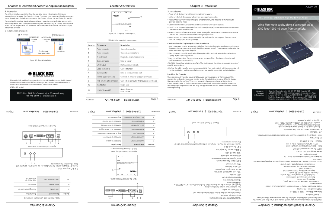
5. Application Diagram
IR receiver |
| IR transceiver |
|
| |
Console | Computer |
|
Unit | Unit |
|
| Computer | |
Console | fiber optic cable |
|
Figure 5-1. Typical installation.
© Copyright 2012. Black Box Corporation. All rights reserved. Black Box® and the Double Diamond logo are registered trademarks of BB Technologies, Inc. Any
FREE! Live, 24/7 Tech Support is just 30 seconds away.
Chapter 2: Overview
11
Figure 2-6. Computer unit top panel.
Table 2-2. Computer Unit components.
Number | Component | Description |
|
|
|
1 | Audio connector | Connects to speaker |
|
|
|
2 | Audio connector | Connects to microphone |
|
|
|
3 | IR control jack | Plug in the external sensor here |
|
|
|
4 | Barrel connector | Links to power |
|
|
|
5 | Link OK LED | Flashing yellow: Link OK |
|
|
|
6 | (2) SC connectors | Connect to fiber |
|
|
|
7 | DVI connector | Links to computer video port |
8(1) USB Type B connector Connects to computer keyboard and mouse
9 | (1) | Connects to computer PS/2 keyboard and mouse | |
|
|
| |
10 | Reset button | Resets unit | |
|
|
| |
11 | Link OK/Power LED | Green: Power on | |
Blue: Link OK | |||
|
| ||
|
|
|
Page 5 |
Chapter 3: Installation
3. Installation
•Power off all devices that will be connected to this system.
•Make sure that all devices you will connect are properly grounded.
•Place units away from fluorescent lights, air conditioners, and machines that are likely to generate electrical noise.
•Determine where the Console Unit and the Computer Unit will be located.
•Use SC to SC duplex
•Make sure that the fiber cable length is long enough for the connection between the Console Unit and the Computer Unit to prevent having to splice fiber.
•Never attempt to disassemble or reassemble the enclosure for any purpose. This may cause personal injury and/or property damage.
Considerations for Duplex Optical Fiber Installation
1.Users may need to order appropriate cable lengths conforming to the application environment; however, the maximum cable length should not exceed 3200 ft. (1000 meters). Otherwise, the video resolution signal may degrade.
2.Do not exceed the cable bend radius. Fiber optic cable can break when kinked or bent too tightly, especially during pulling.
3.Do not twist the cable. Twisting the cable can stress the fibers. Tension on the cable and pulling ropes can cause twisting.
CAUTION: Do not look into the ends of any fiber optic cables. You might be exposed to harmful invisible laser radiation.
4.Follow the cable manufacturer's recommendations. Fiber optic cable is often custom designed for the installation, and the manufacturer may have specific instructions on its installation.
Installing the Extender
Users can connect the video source and keyboard and mouse ports to the Computer Unit; connect the keyboard, mouse, and monitor to the Console Unit; and use an SC to SC duplex fiber optic cable for the
Page 6 |
Using fiber optic cable, place a computer up to 3280 feet (1000 m) away from a console.
Customer Order
Support call
Information a week: Call
4 Page | com.blackbox |
| 3 Page | com.blackbox | 2 Page | com.blackbox | ||||||||||||||||||||||||||||||||||||||||
|
|
|
|
|
|
|
|
|
|
|
|
|
|
|
|
|
|
|
|
|
|
|
|
|
|
|
|
|
|
|
|
|
|
|
|
|
|
|
|
| ||||||
|
|
|
|
|
|
|
|
|
|
|
|
|
|
|
|
|
|
|
|
|
|
|
|
|
|
|
|
|
|
|
|
|
|
|
|
|
|
|
|
|
|
|
|
|
|
|
|
|
|
|
|
|
|
|
|
|
|
|
|
|
|
|
|
|
|
|
|
|
|
|
|
|
|
|
|
|
|
|
|
|
|
|
|
|
|
|
|
|
|
|
|
|
|
|
|
|
|
|
|
|
|
|
|
|
|
|
|
|
|
|
|
|
|
|
|
|
|
|
|
|
|
|
|
| Keyboard/mouse |
| connectors A Type USB (2) | 7 |
|
|
|
|
|
|
|
|
|
|
|
|
|
|
|
|
|
|
|
|
|
|
|
|
|
|
|
|
|
|
|
|
|
|
|
|
|
|
|
|
|
|
|
|
|
|
|
|
|
|
|
|
|
|
|
|
|
|
|
|
|
|
|
|
|
|
|
|
|
|
|
|
|
|
|
|
|
|
|
|
|
|
|
|
|
|
|
|
|
| monitor DVI to Connects |
| connector Video | 6 |
|
|
|
|
| .panel front Unit |
| |||||
|
|
|
|
|
|
|
|
|
|
|
|
|
|
|
|
|
|
|
|
|
|
|
|
|
|
|
|
|
|
|
|
|
|
|
|
|
|
|
|
| ||||||
|
|
| .panel back Unit |
|
|
|
|
| interface fiber to Connects |
| connectors SC (2) | 5 |
|
|
|
|
|
| ||||||||||||||||||||||||||||
|
|
|
|
|
|
|
|
|
|
|
|
|
|
|
|
|
|
|
|
| ||||||||||||||||||||||||||
|
|
|
|
|
|
|
|
|
|
|
|
|
|
|
|
|
|
|
|
|
|
|
| |||||||||||||||||||||||
|
|
|
|
|
|
|
|
|
|
|
|
|
|
|
|
|
|
|
|
|
| 10 |
|
|
|
|
| supply power VDC 9 to Links |
| connector Barrel | 4 |
|
|
|
|
|
|
|
|
|
|
|
| |||
|
|
|
|
|
|
|
|
|
|
|
|
|
|
|
|
|
|
|
|
|
|
|
|
|
|
|
|
|
|
|
|
|
|
|
|
|
|
|
|
|
|
|
|
|
|
|
|
|
|
|
|
|
|
|
|
|
|
|
|
|
|
|
|
|
|
|
|
|
|
|
|
|
|
|
|
|
| here sensor external the in Plug |
| jack control IR | 3 |
|
|
|
|
|
|
|
|
|
|
|
|
|
|
|
|
|
|
|
|
|
|
|
|
|
|
|
|
|
|
|
|
|
|
|
|
|
|
|
|
|
|
| microphone to Connects |
| connector Audio | 2 |
|
|
|
|
|
|
|
|
|
|
|
|
|
|
|
|
|
|
|
|
|
|
|
|
|
|
|
|
|
|
|
|
|
|
|
|
|
|
|
|
|
|
| speaker to Connects |
| connector Audio | 1 |
|
|
| 3 | 2 | 1 |
| .components the describes | ||||
| 9 | 8 |
|
|
|
| 7 | 6 |
|
| 5 | 4 |
|
|
|
|
|
|
|
|
|
|
| |||||||||||||||||||||||
|
|
|
|
|
|
|
|
|
| Descriiption |
| Component | Number | |||||||||||||||||||||||||||||||||
|
|
|
|
|
|
|
|
|
|
|
|
|
|
|
|
|
|
|
|
|
|
|
|
|
|
|
|
|
|
|
| |||||||||||||||
|
|
| .panel front Unit |
|
|
|
|
|
|
|
|
|
|
|
|
|
|
| Unit Console 1.4.2 | |||||||||||||||||||||||||||
|
|
|
|
|
|
|
| .components Unit |
|
|
|
|
|
|
|
|
|
|
|
| ||||||||||||||||||||||||||
|
|
|
|
|
|
|
|
|
|
|
|
|
|
|
|
|
|
|
|
|
|
|
|
|
|
|
|
|
|
|
|
|
|
|
|
|
|
|
|
|
| Description Hardware 4.2 | ||||
|
|
|
|
|
|
|
|
|
|
|
|
|
|
|
|
|
|
|
|
|
|
|
|
|
|
|
|
|
|
| .panel top Unit |
|
|
|
|
|
|
|
|
|
|
| ||||
|
|
|
|
|
|
|
|
|
|
|
|
|
|
|
|
|
|
|
|
|
|
|
|
|
|
|
|
|
|
|
|
|
|
|
|
|
|
|
|
|
|
| cable | |||
|
|
|
|
|
|
|
|
|
|
|
|
|
|
|
|
|
|
|
|
|
|
|
|
|
|
|
|
|
|
|
|
|
|
|
|
|
|
|
|
|
|
|
|
|
| |
1 Page | com.blackbox |
| |||
|
|
| .KVM or PC PS2/USB Supports • | ||
| .1200) x (1920 WUXGA or 1080) x (1920 HD Full of resolution | ||||
| the with computer a from away meters) (1000 feet 3280 | ||||
| to up monitor and mouse keyboard, the locate Remotely • | ||||
| .cable optics fiber via connects pair Extender KVM • | ||||
|
|
|
| Features 1.2 | |
.(keyboard/mouse/monitor) console a from m) (1000 feet 3280 to up computer a Place | |||||
|
|
|
| Overview .2 | |
|
|
| kg) 61.(0 .lb 34.1 — Weight | ||
|
| cm) 13 x 1.13 x 7.(2 1”D.5 x 2”W.5 x 1”H.1 | |||
|
|
| units): Computer and (Console— Sizeunit Each | ||
|
|
| .VDC | ||
|
|
|
| — Supply Power amp | |
|
|
| LED signal optic fiber (1) | ||
3 | 2 | 1 | .components the describes |
|
|
| |
.Unit Computer the of panels top and back, front, the show | |||
| Unit Computer 2.4.2 | 10 | ||
|
|
| ||
OK Link Blue: | LED OK/Power Link | 10 | .panel back Unit | |
on Power Red: | ||||
|
|
| ||
unit Resets | button Reset | 9 | 9 | |
| ||||
OK Link yellow: Flashing | LED OK Link | 8 |
| |
Descriiption | Component | Number |
| |
cable audio and cable DVI • control KVM for keyboard/mouse USB • Requirements System 3.2 manual user’s This • pads foot of sets (2) • test) (for Cable Optic Fiber
.com.info@blackbox or
Included What’s 2.2 ).etc mice, (keyboards, (HIDs) devices interface human Supports • protection surge Supports •
LED, Status Power/Link |
|
.connection |
|
PS/2 than priority higher a has USB simultaneously, connected are PS/2 and USB When NOTE: |
|
speaker for (1) microphone, for (1) Jack: Audio |
|
transmitter; IR for (1) Jack: Control Remote |
|
included), |
|
PS/2 (1) plus USB (1) Mouse: and Keyboard |
|
female, DVI (1) Monitor: unit: Computer |
|
speaker; for (1) microphone, for (1) Jack: Audio |
|
receiver, IR for (1) Jack: Control Remote |
|
female, DVI (1) Monitor: |
|
A, Type USB (2) Keyboard/Mouse: unit: Console |
|
— Connectors |
|
1080) x (1920 HD 1200)/Full x (1920 WUXGA — ).(Max Resolution Video |
|
optics Fiber — Connection Unit |
|
— Distance Extension | ) |
Specifications .1 |
|
.components Unit Console .(continued) | 7 | 6 | 5 | 8 | 4 | .display |
.eye the to injury cause can beam laser The .radiation laser invisible to exposed be might |
You .cables optic fiber any of ends the into directly view or beam into stare not Do CAUTION: |
Overview 2: Chapter | Overview 2: Chapter | Overview 2: Chapter | Overview 2: Chapter Specifications; 1: Chapter |