CHAPTER 3: Configuration
5.Normally, the Converter’s frame ground is isolated from its RS-232 signal ground. But if you want to connect frame ground to signal ground, you’ll need to solder a 100-ohm, 500-mW resistor to the terminals of location W7. (You could also use a wire jumper, but you’d need to make sure that any ground-loop currents caused by voltage-potential differences between the RS-232 and RS-422/485 sides are limited to acceptable levels—a strong ground loop could damage the Converter and attached equipment.)
CAUTION!
Any soldering should be done only by qualified, experienced personnel.
6.If your Converter is a standalone IC107A-R3 or IC107AE-R3 model: Put the top of the Converter’s case back on and secure it in place by screwing the bottom screw back in.
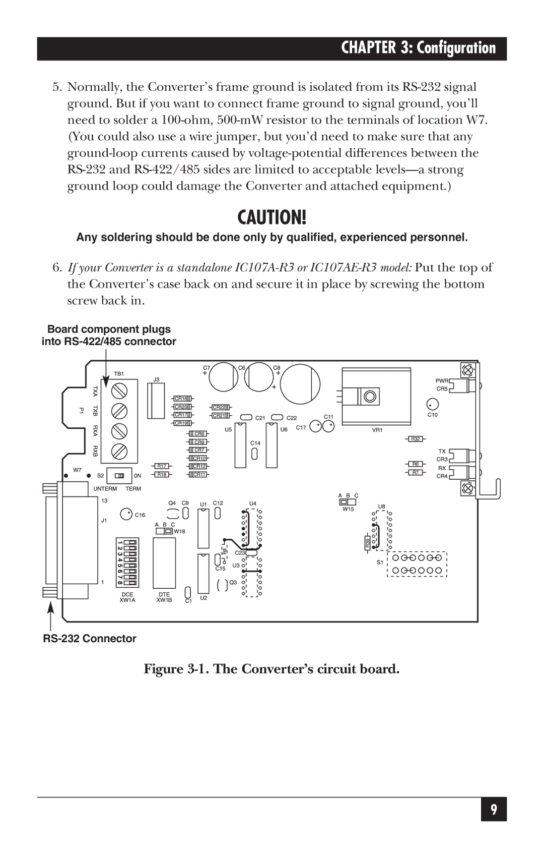
Board component plugs into RS-422/485 connector
RS-232 Connector
Figure 3-1. The Converter’s circuit board.