Chapter 2: Overview
1
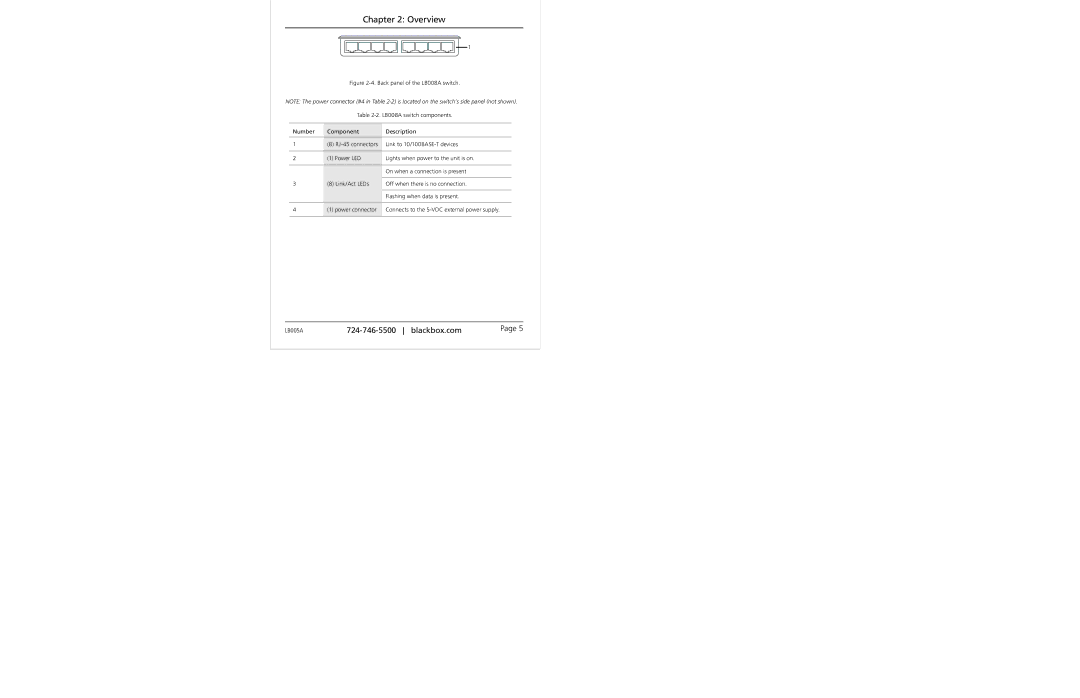
Figure 2-4. Back panel of the LB008A switch.
NOTE: The power connector (#4 in Table
Table 2-2. LB008A switch components.
Number | Component | Description |
|
|
|
1 | (8) | Link to |
|
|
|
2 | (1) Power LED | Lights when power to the unit is on. |
|
|
|
|
| On when a connection is present |
3(8) Link/Act LEDs Off when there is no connection. Flashing when data is present.
4 | (1) power connector Connects to the |
|
|
LB005A | Page 5 |
