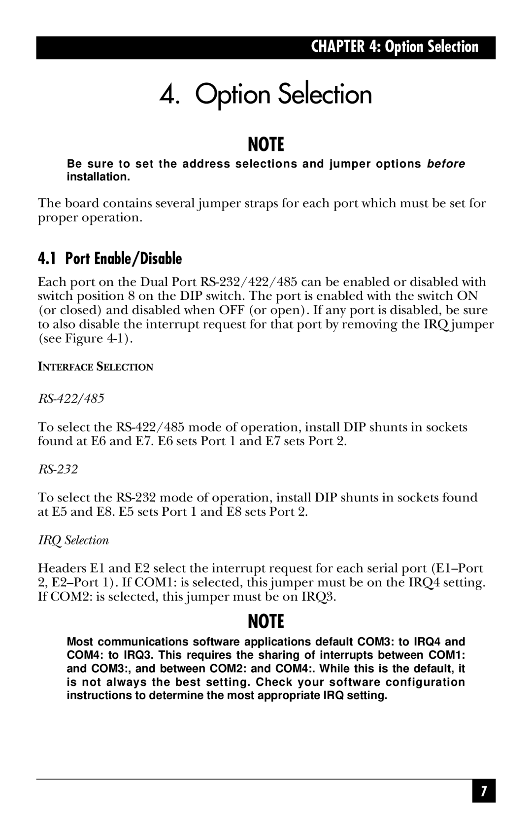
IC113C, RS-485, IC175C specifications
The Black Box IC113C and IC175C are part of a series of versatile RS-485 interface converters designed to facilitate reliable data transmission over long distances. RS-485 is a standard defining the electrical characteristics of drivers and receivers for use in serial communications systems, and these specific Black Box converters exemplify the technology's adaptability and robustness.The IC113C is an RS-485 to RS-232 converter, providing a seamless transition between these two common serial communication protocols. With a compact design, it boasts an operating temperature range of -40 to 85 degrees Celsius, making it suitable for harsh environmental conditions. Its key feature includes the ability to extend the communication distance up to 4,000 feet, which is ideal for industrial applications where devices may be far apart. Additionally, the IC113C includes built-in surge protection, ensuring that the device can withstand electrical noise and spikes, ultimately increasing the system's reliability.
On the other hand, the Black Box IC175C serves as an RS-485 to USB converter, bridging older serial devices with modern USB interfaces. This converter is critical for users wanting to connect legacy equipment to contemporary computing systems. Featuring a plug-and-play design, the IC175C is easy to install with no external power supply required, as it is powered directly through the USB connection. It also supports data rates up to 115.2 Kbps, ensuring fast and efficient data transfer.
Both models employ differential signaling, which enhances noise immunity and allows for greater transmission distances compared to single-ended communication standards. Furthermore, the converters support multiple nodes on the same bus, accommodating a network of devices without requiring complex wiring schemes.
In summary, the Black Box IC113C and IC175C offer essential features that cater to diverse industrial and commercial applications. With their robust construction, extensive operating ranges, and compatibility with various communication protocols, these converters enhance system interoperability and provide durable solutions for long-distance data communication needs. Whether connecting legacy systems or extending communication capabilities, these devices exemplify reliability and efficiency in modern data transmission technologies.

