Chapter 2: Overview
Table 2-1. LGB516A components.
Number in Figures |
|
|
| |
and | Component | Status | Description | |
|
|
|
| |
1 | (1) Power LED | On | Lights when power to unit is on. | |
|
|
|
| |
2 | (4) FIber LEDs (F1– | On | Fiber port(s) are active. | |
|
| |||
F4) | Flashing | Switch is passing data. | ||
| ||||
|
| |||
|
|
|
| |
3 | (16) 1000M LEDs | On | Link is running at 1000 Mbps. | |
|
| |||
Off | Link is running at 10/100 Mbps. | |||
|
| |||
|
|
|
| |
|
| On | Light when SFP is connected. | |
4 | (16) Link/Act LEDs |
|
| |
Flashing | Switch is passing data. | |||
|
| |||
|
|
|
| |
5 | (12) | — | Links to | |
|
|
|
| |
6 | (4) | — | Link to either | |
combo ports | ||||
|
|
| ||
|
|
|
| |
|
| ON | Power to switch is on. | |
7 | ON/OFF switch |
|
| |
OFF | Power to switch is off. | |||
|
| |||
|
|
|
| |
8 | AC input connector | — | ||
|
|
|
|
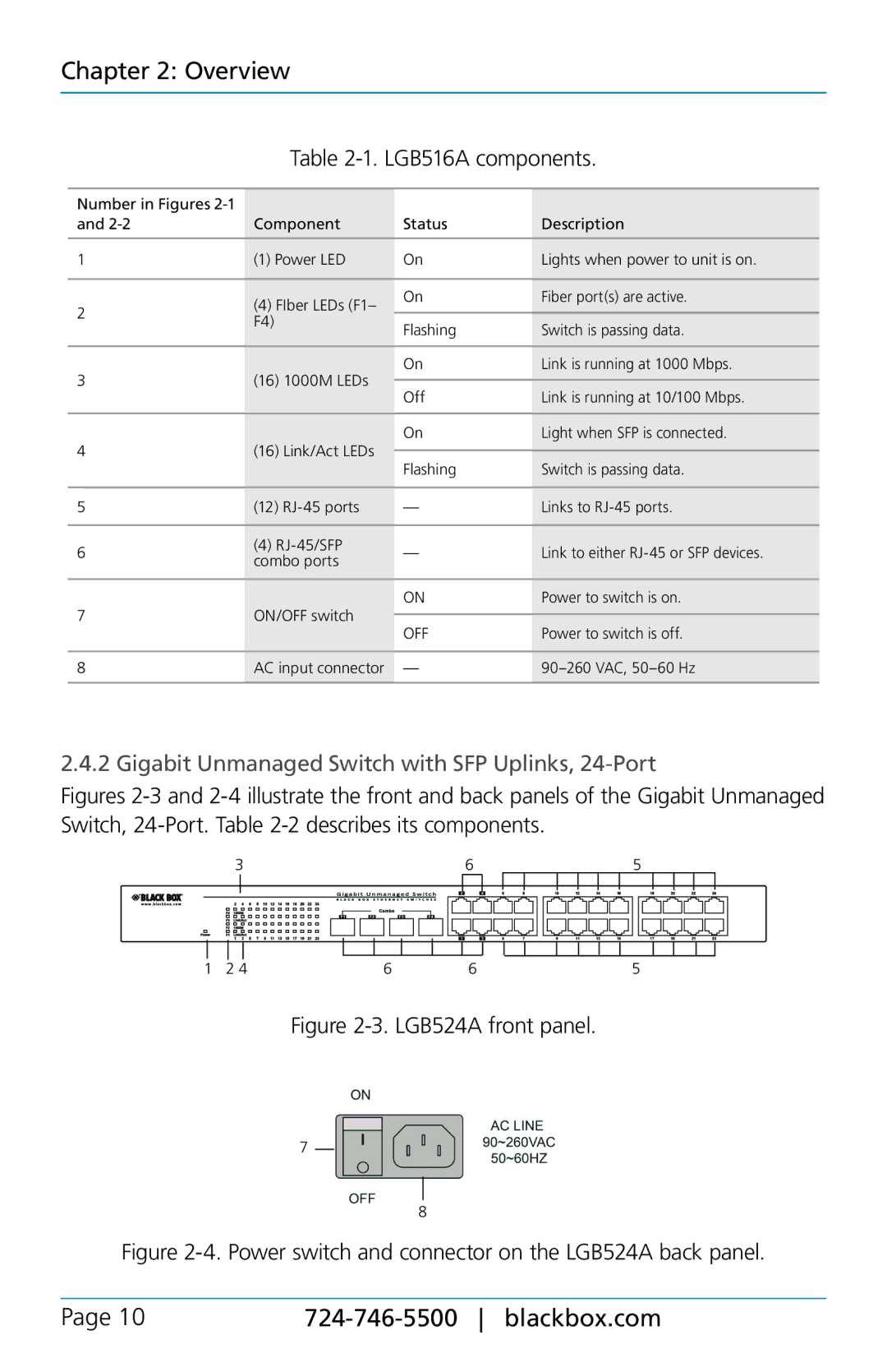
2.4.2 Gigabit Unmanaged Switch with SFP Uplinks, 24-Port
Figures 2-3 and 2-4 illustrate the front and back panels of the Gigabit Unmanaged Switch, 24-Port. Table 2-2 describes its components.
|
| 3 |
|
|
|
|
|
|
|
|
| 6 |
|
|
|
|
|
| 5 |
|
|
|
|
|
|
|
| ||||||||||||||||||
|
|
|
|
|
|
|
|
|
|
|
|
|
|
|
|
|
|
|
|
|
|
|
|
|
|
|
|
|
|
|
|
|
|
|
|
|
|
|
|
|
|
|
|
|
|
|
|
|
|
|
|
|
|
|
|
|
|
|
|
|
|
|
|
|
|
|
|
|
|
|
|
|
|
|
|
|
|
|
|
|
|
|
|
|
|
|
|
|
|
|
|
|
|
|
|
|
|
|
|
|
|
|
|
|
|
|
|
|
|
|
|
|
|
|
|
|
|
|
|
|
|
|
|
|
|
|
|
|
|
|
|
|
|
|
|
|
|
|
|
|
|
|
|
|
|
|
|
|
|
|
|
|
|
|
|
|
|
|
|
|
|
|
|
|
|
|
|
|
|
|
|
|
|
|
|
|
|
|
|
|
|
|
|
|
|
|
|
|
|
|
|
|
|
|
|
|
|
|
|
|
|
|
|
|
|
|
|
|
|
|
|
|
|
|
|
|
|
|
|
|
|
|
|
|
|
|
|
|
|
|
|
|
|
|
|
|
|
|
|
|
|
|
|
|
|
|
|
|
|
|
|
|
|
|
|
|
|
|
|
|
|
|
|
|
|
|
|
|
|
|
|
|
|
| |
|
|
|
|
|
|
|
|
|
|
|
|
|
|
|
|
|
|
|
|
|
|
|
|
|
|
|
|
|
|
|
|
|
|
|
|
|
|
|
|
|
|
|
|
|
|
|
|
|
|
|
|
|
|
|
|
|
|
|
|
|
|
|
|
|
|
|
|
|
|
|
|
|
|
|
|
| |||||||||||||||
|
|
|
|
|
|
|
|
|
|
|
|
|
|
|
|
|
|
|
|
|
|
|
|
|
|
|
|
|
|
|
|
|
|
|
|
|
|
|
|
|
|
|
|
|
|
1 |
| 2 4 |
| 6 | 6 |
|
|
|
|
|
| 5 |
|
|
|
|
|
|
|
| |||||||||||||||||||||||||
Figure 2-3. LGB524A front panel.
7
8
Figure 2-4. Power switch and connector on the LGB524A back panel.
Page 10 |
|