Page 1 of 3

Marine Electrical Products

AC Rotary Switch

3 Positions + OFF, 2 Pole

WARNING

]These instructions are intended to provide assistance with the installation of this product, and are not a substitute for a more

comprehensive understanding of electrical systems. We strongly recommend that a competent electrical professional perform the

Features

PN 9010

installation of this product.

]If either the switch front or back is to be exposed to water it must be protected with a waterproof shield.

Switches 3 - 120V AC Sources

Compact solution when circuit protection is provided elsewhere

Allows connecting one of three different AC sources to one circuit

Heavy duty industrial rated switches

Intuitive function - One handed operation

UL listed switches

Specifications

Amperage Rating:

32 Amperes Maximum

Voltage Rating:

600 Volts AC Maximum

Maximum Wire Size:

10 AWG


Minimum Wire Size:

14 AWG


Terminal Recommended Torque:

12 lb-in.


Overall Dimensions:

Inches

Millimeters

1.890 x 1.890

48.00 x 48.00

Mounting Depth:

2.41

61.2

Maximum Panel Thickness:

0.157

4.00

6684 Rev 002

Installation

1.Disconnect all AC and DC power

Disconnect all AC power originating on or off the vessel. This includes inverters, generators, shore power attachments and any other device capable of supplying AC power to the ship’s circuits.

Disconnect the main positive DC cable from all batteries to eliminate the possibility of a short circuit and to disable the inverter while installing the switch.

2.Select mounting location and cut opening

Select a mounting location which is protected from water on the front and back of the switch and is not in an area where flammable vapors from propane, gasoline or lead acid batteries accumulate. AC rotary switches are not ignition protected and may ignite such vapors.

Using the template provided, drill the mounting surface where the switch is to be mounted. The mounting surface maximum thickness is 0.157” (4.00mm). Do not yet fasten the switch to the mounting surface.

3.Install source 1, source 2, source 3, and output wires

Install the feed wires from AC Shore Power and AC Generator. Install the output wires. Refer to the wire sizing chart to select the proper wire size. Connect the black AC hot, white AC neutral and green AC safety ground as shown in the illustration. To avoid excess wire temperatures when cooling may be limited, we recommend using at least 12 gauge wire for 30A.

Do not confuse the neutral current carrying wires (sometimes called ground) with the green normally non-current carrying wires (sometimes called grounding). These two wires must be connected only at the source of power, nowhere else.

A double pole circuit breaker must be installed within 10 feet of the shore power inlet, ahead of this switch. The measurement is made along the conductors.

]The switch must not be installed in explosive environments such as gasoline engine rooms or battery compartments as the switches are not ignition proof.

]The vessel’s shore power cord must be disconnected form shoreside power before installing this electrical switch.

]If an inverter is installed on the vessel its power leads must be disconnected at the battery before the panel installation. Be aware that many inverters have a “sleep mode” in which their voltage potential

may not be detectable with measuring equipment.

]If an AC Generator is installed aboard it must be stopped and rendered

inoperable before the switch is installed.

]Verify that no other AC or DC source is connected to the vessel’s wiring before the switch is installed.

Guarantee:

Blue Sea Systems stands behind its products for as long as you own them. Find detailed information at www.bluesea.com/about.

For customer service, call 800-222-7617.

Blue Sea Systems Inc.

Phone (360)

738-8230

425 Sequoia Drive

Fax (360)

734-4195

Bellingham, WA 98226 USA

www.bluesea.com

The switch provides switching, but does not provide circuit protection. It is not a substitute for a main circuit breaker.

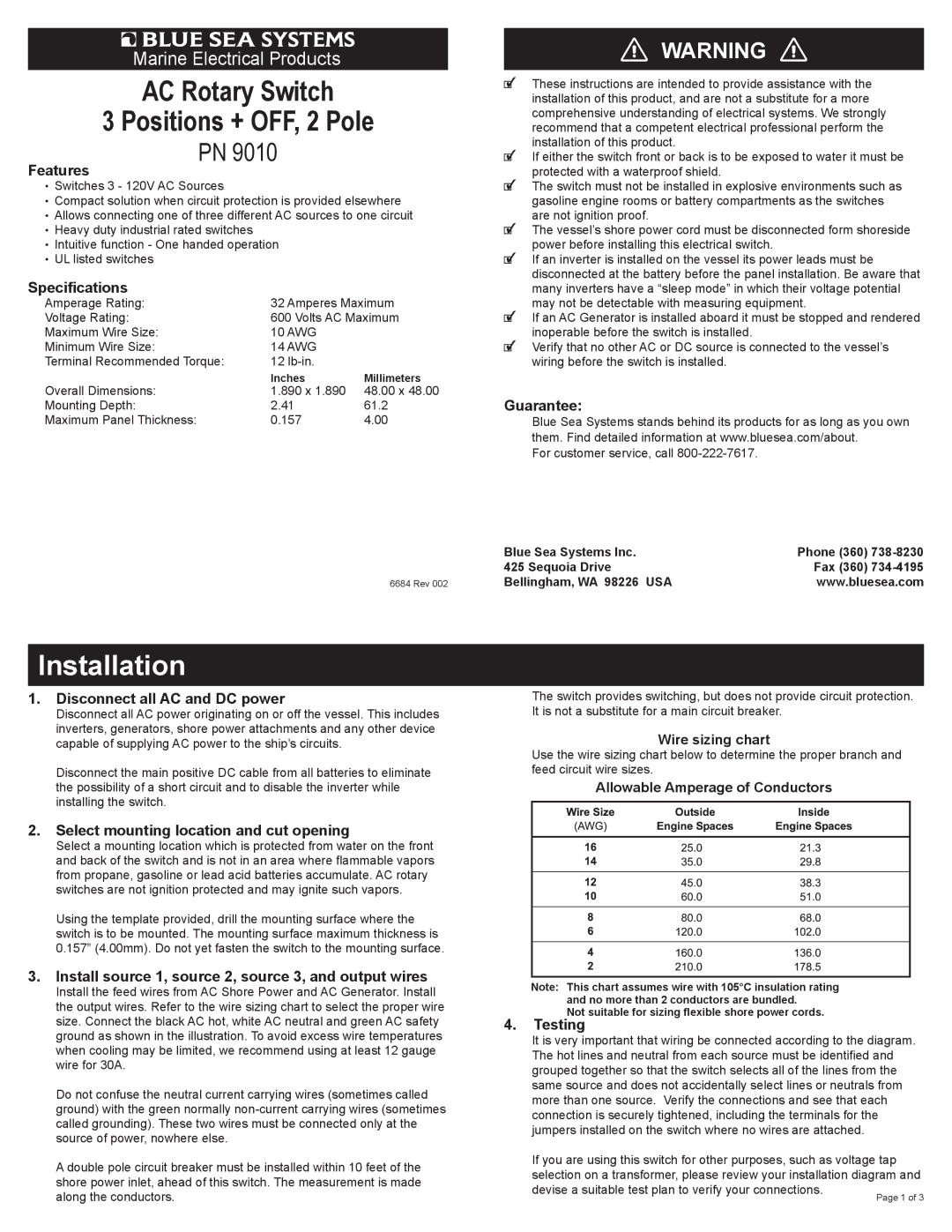
Wire sizing chart

Use the wire sizing chart below to determine the proper branch and feed circuit wire sizes.

Allowable Amperage of Conductors

Note: This chart assumes wire with 105°C insulation rating and no more than 2 conductors are bundled.

Not suitable for sizing flexible shore power cords.

4. Testing

It is very important that wiring be connected according to the diagram. The hot lines and neutral from each source must be identified and grouped together so that the switch selects all of the lines from the same source and does not accidentally select lines or neutrals from more than one source. Verify the connections and see that each connection is securely tightened, including the terminals for the jumpers installed on the switch where no wires are attached.

If you are using this switch for other purposes, such as voltage tap selection on a transformer, please review your installation diagram and devise a suitable test plan to verify your connections.

Page 1
Image 1
Blue Sea Systems PN 9010, PN9010 dimensions Features, Specifications, Disconnect all AC and DC power, Guarantee, Testing

PN 9010, PN9010 specifications

Blue Sea Systems PN9010 is a highly regarded marine electrical component that offers reliability and advanced features for boaters and marine enthusiasts. Designed specifically for use in marine applications, the PN9010 serves as a critical element in ensuring the safety and efficiency of electrical systems on board.

One of the main features of the PN9010 is its robust construction. Built to withstand the harsh conditions of the marine environment, this electrical product is resistant to corrosion and can handle high levels of moisture. The use of high-quality materials ensures that it remains functional even under extreme conditions, making it a trusted choice for boaters.

The PN9010 is equipped with advanced circuit protection technology. This feature is essential to prevent overloading and short circuits, which can lead to hazardous situations on board. With its ability to monitor and manage electrical flow, the PN9010 ensures that all connected devices operate smoothly without any risk of damage to the electrical system.

Another key characteristic of the PN9010 is its user-friendly design. The device is straightforward to install, with clear labels and a user-friendly interface that simplifies the setup process. This makes it accessible for both experienced marine electricians and novice boat owners who may not have extensive technical knowledge.

In addition to these features, the PN9010 incorporates innovative technologies that improve overall functionality. The integration of smart technology allows for enhanced monitoring capabilities, enabling users to keep track of their electrical system’s performance in real-time. This contributes to better decision-making when it comes to managing power consumption and ensuring continuous operation.

The compact design of the PN9010 allows for easy integration into existing systems without requiring significant modifications. Its versatility makes it suitable for a wide range of marine applications, from small boats to larger vessels. This adaptability ensures that users can rely on the PN9010 to meet diverse electrical needs while maintaining the highest levels of performance.

Overall, the Blue Sea Systems PN9010 stands out as an essential component in marine electrical systems. With its sturdy construction, advanced protection features, user-friendly design, and cutting-edge technology, it offers an unmatched combination of reliability and effectiveness for boaters and marine professionals alike. Whether you are upgrading your vessel or building a new electrical system, the PN9010 is a top choice for ensuring optimal performance and safety on the water.