Marine Electrical Products
DC Power Distribution Panel
PN 8261 8 Position Water Resistant
PN 8262 4 Position Water Resistant
Panel Specifications
Material: | 0.100” | ||
Primary Finish: | Chemical Treatment per Mil Spec | ||
Final Panel Finish: | Graphite color 2 part textured Polyurethane | ||
Fuse Holder: | Accepts commonly available AGC (fast acting) and | ||
| MDL (slow blow) | ||
Fuses: | 15 Ampere AGC (fast acting) fuses installed. | ||
Amperage Rating: | Switches and Fuse Holders, | ||
| 20 amperes maximum for 12 volt system | ||
| 15 amperes maximum for 24 volt system | ||
Cumulative Rating: | 45 Amperes |
| |
Voltage Rating: | Panels are rated for 12 or 24 volts DC. | ||
Circuit Indicator: | LED embedded in switch, rated 100,000 hour 1/2 life | ||
Panel Depth: | 69.90mm |
| |
Overall Dimensions: | PN | Inches | Millimeters |
8261 | 238.00 x 95.30 | ||
| 8262 | 133.40 x 95.30 | |
Mounting Centers: | 8261 | 216.90 x 74.20 | |
| 8262 | 112.30 x 74.20 | |
Water Resistant: | Will withstand the water exposures normally | ||
| encountered in above deck applications: Salt spray, | ||
| rain, hose washdowns, momentary immersions. | ||
The Purpose of a Panel
There are five purposes of a marine electrical panel:
•Power distribution
•Circuit (wire) protection
•Circuit ON/OFF switching
•Metering of voltage and amperage (In panels with meters)
•Condition Indication (circuit energized)
Document 9836 Rev.F
![]() WARNING
WARNING ![]()
@It is not possible within the scope of these instructions to fully acquaint the installer with all the knowledge of electrical systems that may be necessary to correctly install this product. If the installer is not knowledgeable in electrical systems we recommend that an electrical professional be retained to make the installation.
@If the panel front is to be exposed to water it must be properly sealed to the instrument panel surface. The included gasket must be in place and the panel screwed down tight.
@The panels must not be installed in explosive environments such as gas engine rooms or battery compartments as the switches are not ignition proof.
@The main positive connection must be disconnected at the battery post to avoid the possibility of a short circuit during the installation of this distribution panel.
Guarantee
Any Blue Sea Systems product with which a customer is not satisfied may be returned for a refund or replacement at any time.
Useful Reference Books
Calder, Nigel, 1996: Boatowner’s Mechanical and Electrical Manual, 2nd edition, Blue Ridge Summit, PA: TAB Books, Inc.
Wing, Charlie, 1993: Boatowner’s Illustrated Handbook of Wiring, Blue Ridge Summit, PA: TAB Books, Inc.
Related Products from Blue Sea Systems
PanelBack Insulating Covers
High Amperage Fuses and Circuit Breakers for positive feed wires High Amperage Battery Switches
Terminal Blocks and Common Bus Connectors AC Distribution Panels
DC Distribution Panels
AC and DC Voltmeters and Ammeters
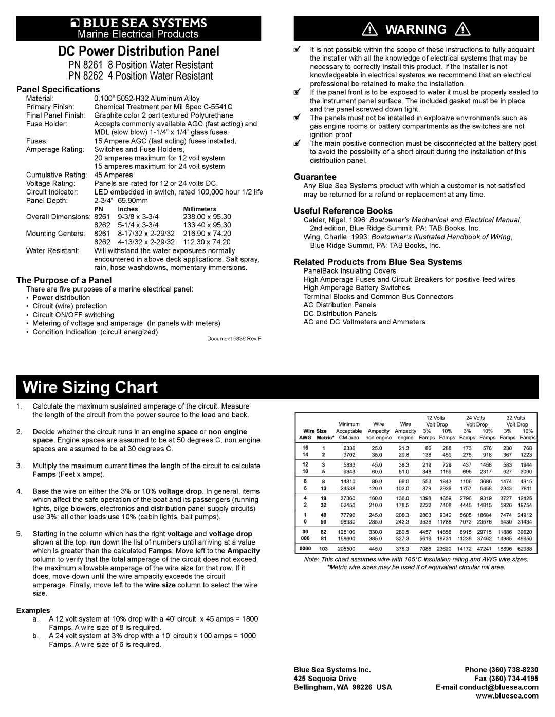
Wire Sizing Chart
1.Calculate the maximum sustained amperage of the circuit. Measure the length of the circuit from the power source to the load and back.
2.Decide whether the circuit runs in an engine space or non engine space. Engine spaces are assumed to be at 50 degrees C, non engine spaces are assumed to be at 30 degrees C.
3.Multiply the maximum current times the length of the circuit to calculate Famps (Feet x amps).
4.Base the wire on either the 3% or 10% voltage drop. In general, items which affect the safe operation of the boat and its passengers (running lights, bilge blowers, electronics and distribution panel supply circuits) use 3%; all other loads use 10% (cabin lights, bait pumps).
5.Starting in the column which has the right voltage and voltage drop shown at the top, run down the list of numbers until arriving at a value which is greater than the calculated Famps. Move left to the Ampacity column to verify that the total amperage of the circuit does not exceed the maximum allowable amperage of the wire size for that row. If it does, move down until the wire ampacity exceeds the circuit amperage. Finally, move left to the wire size column to select the wire size.
Examples
a.A 12 volt system at 10% drop with a 40’ circuit x 45 amps = 1800 Famps. A wire size of 8 is required.
b.A 24 volt system at 3% drop with a 10’ circuit x 100 amps = 1000 Famps. A wire size of 6 is required.
Note: This chart assumes wire with 105°C insulation rating and AWG wire sizes.
*Metric wire sizes may be used if of equivalent circular mil area.
Blue Sea Systems Inc. | Phone (360) | |
425 Sequoia Drive | Fax (360) | |
Bellingham, WA 98226 USA | ||
| www.bluesea.com | |