GXP specifications
The BodyCraft GXP is a versatile multi-gym system designed to cater to fitness enthusiasts of all levels. This innovative piece of equipment combines functionality, durability, and technological advancements to provide a comprehensive workout experience at home or in a professional gym setting.The GXP features a sturdy frame constructed from heavy-duty steel, ensuring stability and longevity even under the most intense workout sessions. Its powder-coated finish not only adds to its aesthetic appeal but also protects against scratches and corrosion, making it suitable for various environments.
One of the standout features of the BodyCraft GXP is its space-saving design. While it offers a wide array of exercise options, it does so in a compact footprint, making it ideal for home gyms where space is at a premium. The GXP includes a variety of adjustable components, allowing users to tailor their workouts to target specific muscle groups or focus on full-body training.
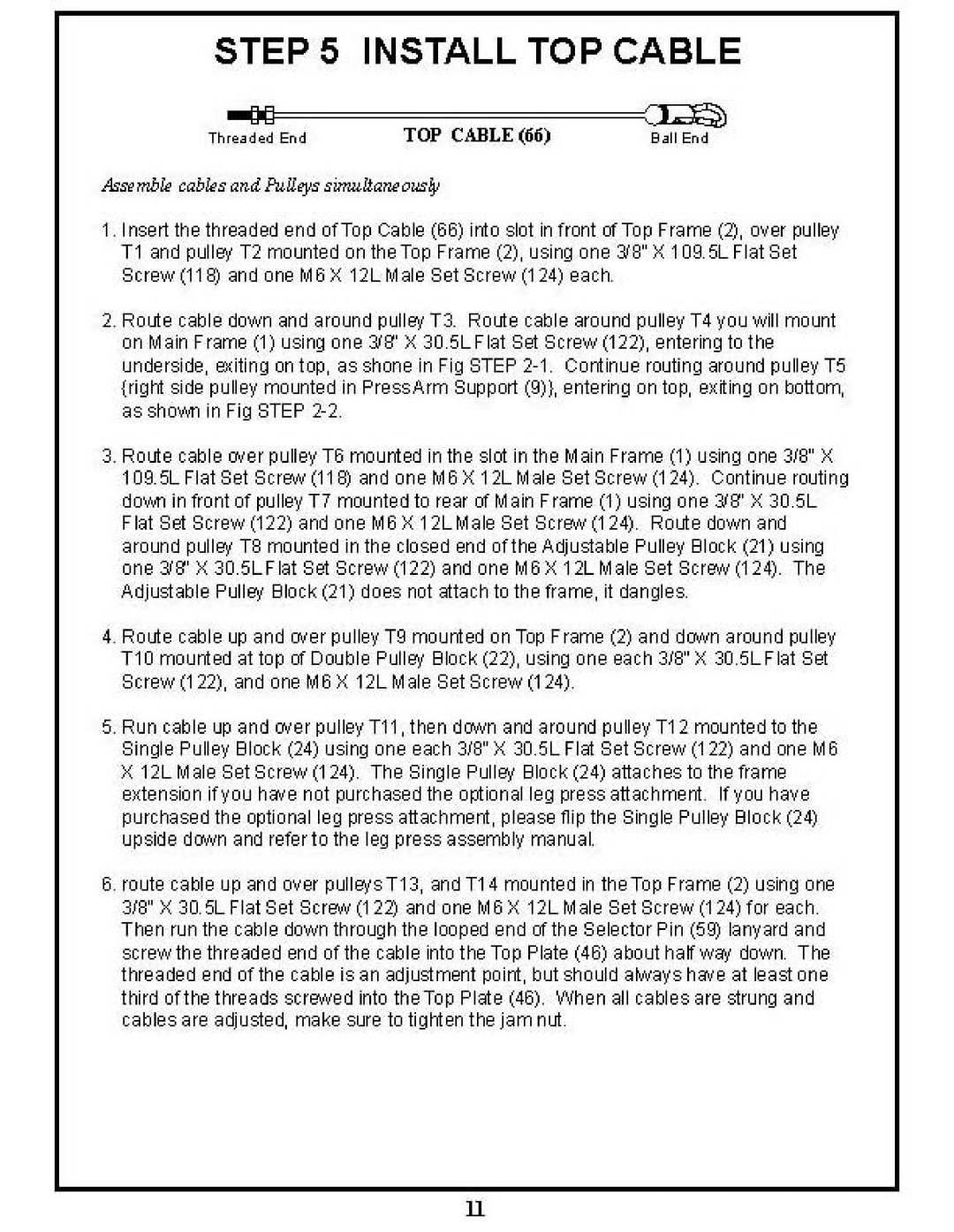
Technologically, the GXP incorporates a unique adjustable pulley system that provides smooth movements and allows users to customize resistance for different exercises. The adjustable arms can be set at various angles, enabling users to perform a diverse range of exercises, including chest presses, seated rows, shoulder raises, and leg extensions. This versatility is a major draw for users who wish to perform a comprehensive workout without needing multiple machines.
Another key feature is the included weight stack, which can be adjusted to meet varying strength levels. The GXP usually comes with a standard 150-pound weight stack, but there are options to upgrade, ensuring that users of all strength levels can benefit from the machine.
The BodyCraft GXP is not just about strength training; it’s also designed with comfort in mind. The padded seats and backrests provide support during use, reducing the risk of injury and ensuring a pleasant workout experience. The ergonomic design of the equipment promotes proper form, which is essential for effective training and injury prevention.
In summary, the BodyCraft GXP is an all-in-one solution for those looking to enhance their fitness journey. With its robust construction, advanced features, and user-friendly design, it serves as an essential addition to any workout regimen, making fitness accessible and engaging for everyone. Whether you're a seasoned athlete or a beginner, the GXP will help you reach your fitness goals with pride.

