Amplified Horn Speakers
Models AH5A, AH15A
Installation and Use Manual
Description
The AH5A and AH15A are
Installation Instructions
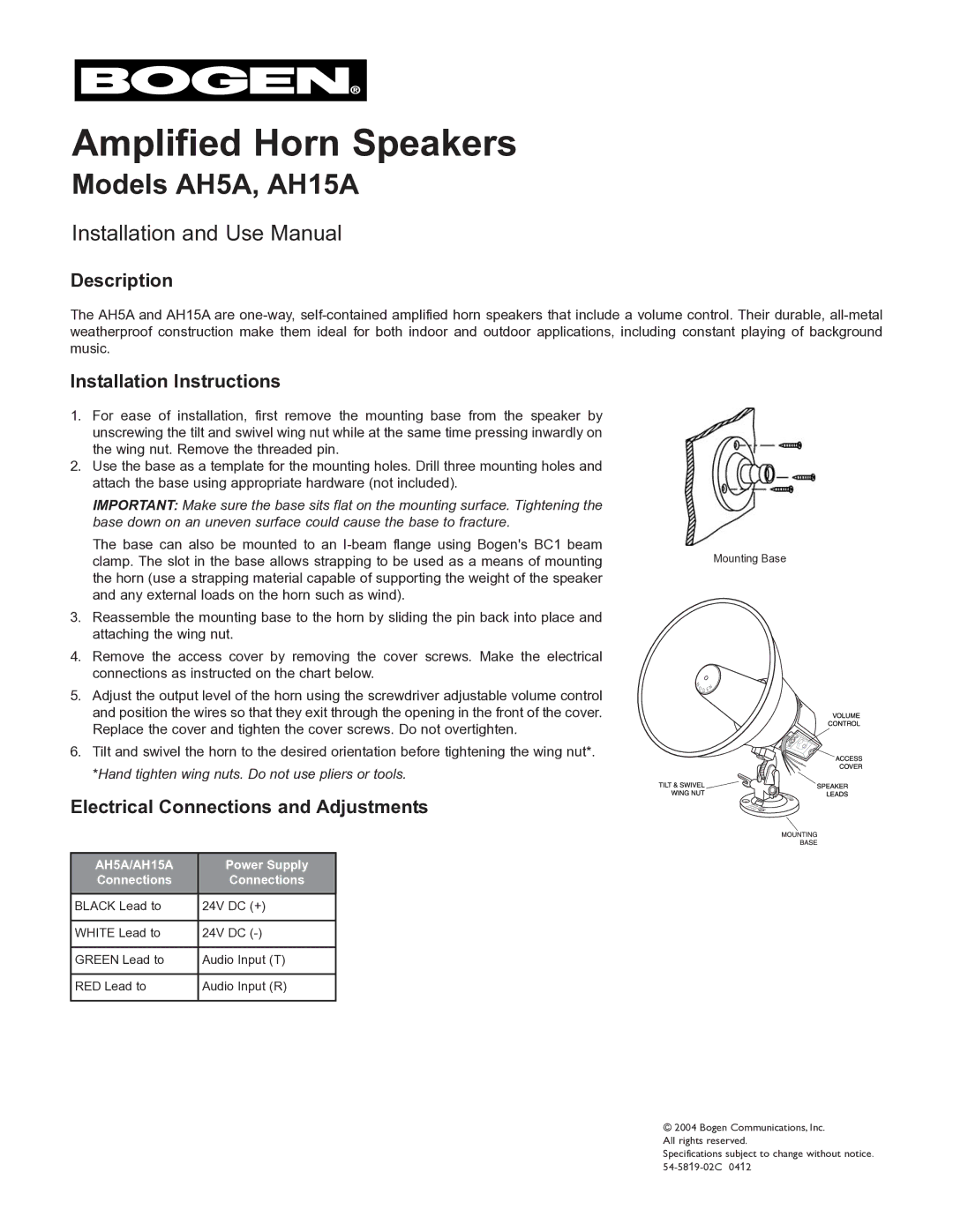
1.For ease of installation, first remove the mounting base from the speaker by unscrewing the tilt and swivel wing nut while at the same time pressing inwardly on the wing nut. Remove the threaded pin.
2.Use the base as a template for the mounting holes. Drill three mounting holes and attach the base using appropriate hardware (not included).
IMPORTANT: Make sure the base sits flat on the mounting surface. Tightening the base down on an uneven surface could cause the base to fracture.
The base can also be mounted to an
3.Reassemble the mounting base to the horn by sliding the pin back into place and attaching the wing nut.
4.Remove the access cover by removing the cover screws. Make the electrical connections as instructed on the chart below.
5.Adjust the output level of the horn using the screwdriver adjustable volume control and position the wires so that they exit through the opening in the front of the cover. Replace the cover and tighten the cover screws. Do not overtighten.
6.Tilt and swivel the horn to the desired orientation before tightening the wing nut*. *Hand tighten wing nuts. Do not use pliers or tools.
Electrical Connections and Adjustments
Mounting Base
AH5A/AH15A |
| Power Supply |
Connections |
| Connections |
BLACK Lead to | 24V | DC (+) |
|
|
|
WHITE Lead to | 24V | DC |
|
| |
GREEN Lead to | Audio Input (T) | |
|
| |
RED Lead to | Audio Input (R) | |
|
|
|
© 2004 Bogen Communications, Inc. All rights reserved.
Specifications subject to change without notice.