Speaker Installation
STEP 1 - For easier installation, remove the flange (base) Figure 3 from the speaker by unscrewing the wing nut while at the
same time pressing inwardly on the wing nut. Place the flange flush with the mounting surface and mark the location of the three holes with either a marker or chisel. It is important that the three holes be exactly aligned with the flange, otherwise you might stress the base or make the connection unsteady. Drill the necessary holes and screw the flange to the surface (see Figure 3). (Use appropriate hardware for your specific mounting surface.)
NOTE: The speaker may also be
STEP 2 - After mounting the flange, reattach the speaker to the flange and aim the speaker for the desired coverage. A 45o downward angle is recommended, but this may vary depend- ing upon speaker layout and floor plan.
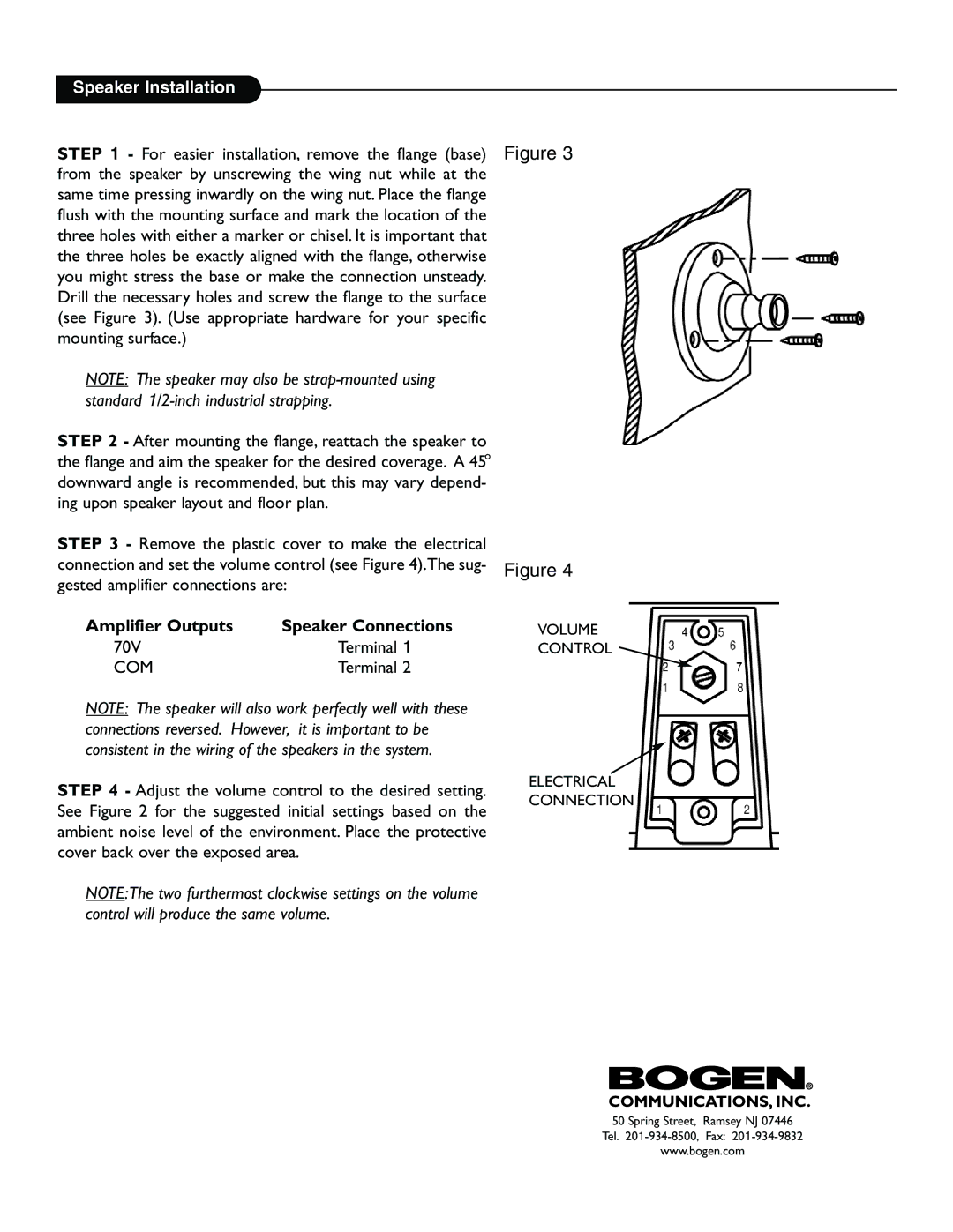
STEP 3 - Remove the plastic cover to make the electrical
connection and set the volume control (see Figure 4).The sug- Figure 4 gested amplifier connections are:
Amplifier Outputs | Speaker Connections | VOLUME |
70V | Terminal 1 | CONTROL |
COM | Terminal 2 |
|
NOTE: The speaker will also work perfectly well with these connections reversed. However, it is important to be consistent in the wiring of the speakers in the system.
STEP 4 - Adjust the volume control to the desired setting. See Figure 2 for the suggested initial settings based on the ambient noise level of the environment. Place the protective cover back over the exposed area.
NOTE:The two furthermost clockwise settings on the volume control will produce the same volume.
ELECTRICAL CONNECTION
50 Spring Street, Ramsey NJ 07446
Tel.
www.bogen.com