| Section 5: Maintenance | 13 |
|
|
|
|
|
|
WARNING
Before inspecting, cleaning or servicing the machine, shut off engine, wait for all moving parts to come to a complete stop, disconnect spark plug wire and move wire away from spark plug.
Failure to follow these instructions can result in serious personal injury or property damage.
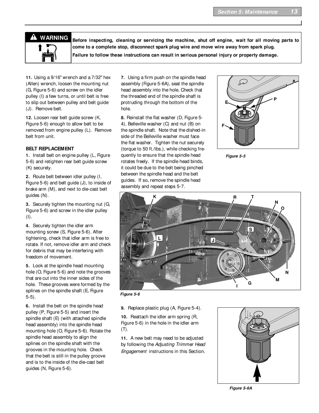
11.Using a 9/16" wrench and a 7/32" hex (Allen) wrench, loosen the mounting nut (G, Figure
(J). Remove belt.
12.Loosen rear belt guide screw (K, Figure
BELT REPLACEMENT
1. Install belt on engine pulley (L, Figure |
(K) securely. |
2. Route belt between idler pulley (I, |
Figure |
brake arm (M), and next to |
7.Using a firm push on the spindle head assembly (Figure
8.Reinstall the flat washer (D, Figure 5- 4), Belleville washer (C) and nut (B) on the spindle shaft. Note that the
E | P |
| |
F |
|
Figure |
|
guides (N). |
3. Securely tighten the mounting nut (G, |
Figure |
(I). |
4. Securely tighten the idler arm |
mounting screw (S, Figure |
KR T
N
O
S
tightening, check that idler arm is free to |
rotate. If not, remove idler arm and check |
for debris that may be interfering with |
freedom of movement. |
5. Look at the spindle head mounting |
hole (O, Figure |
that are cut into the inner sides of the |
hole. These grooves were formed by the |
splines on the spindle shaft (E, Figure |
6. Install the belt on the spindle head |
pulley (P, Figure |
spindle shaft (E) (with attached spindle |
head assembly) into the spindle head |
mounting hole (O, Figure |
spindle head assembly to align the |
splines on the spindle shaft with the |
grooves in the mounting hole. Check |
that the belt is still in the pulley groove |
and is to the inside of the |
guides (N, Figure |
L | J |
|
I G
Figure
9.Replace plastic plug (A, Figure 5-4).
10. Reattach the idler arm spring (R, Figure
(T).
11. A new belt may need to be adjusted by following the Adjusting Trimmer Head
Engagement instructions in this Section.
N
M
