NOTE: The gas pressures specified below refer to pressures taken at the test pressure nipple on the gas inlet pipe just above the regulator (See Fig 4). These readings should be taken while the heater is operating at full input — i.e. with the gas control positioned all the way to the right.

MAXIMUM INLET GAS FLOW PRESSURE SETTING

Altitude

Natural Gas

Liquid Propane


inches W.C:

inches W.C:

0' - 2.000 ft

5.7"

10.5"

2.000 ft - 4.500 ft

4.6"

8.4"

Above 4.500 ft consult your local gas supplier.

GAS LINE SIZING

-It is strongly recommended that the Natural Gas pipe be Black Iron pipe the entire distance from the outside meter to the inlet of the Aquastar regulator. 1/2” Black Iron pipe up to 10 feet, 3/4” Black Iron pipe up to 40 feet and 1” Black Iron pipe up to 150 feet distances. Flex line tubing is NOT recommended, but if used then oversize it.

-It is strongly recommended that the LP Gas pipe be semi-rigid copper or Black Iron pipe from the outside regulator to the inlet of the Aquastar regulator. For semi-rigid copper piping: 5/8” up to 20 feet and 3/4” up to 60 feet distances. For Black Iron piping: 1/2” up to 45 feet and 3/4” up to 160 feet distances. Flex line tubing is NOT recommended, but if used then oversize it.

THESE FIGURES ARE FOR AQUASTAR SUPPLY ONLY, ALL OTHER APPLIANCES IN THE BUILDING WILL NEED TO BE INCLUDED IN THE PIPE SIZING.

National Fuel Gas Code requires that a sediment trap (drip leg) be installed on gas appliances not so equipped. The drip leg must be accessible and not subject to freezing conditions. Install in accordance with the recommendations of the serving gas supplier.

WARNING: The heater must be disconnected from the gas supply piping system during any pressure testing of that system at test pressures in excess of 0.5 psig.

The water heater must be isolated from the gas supply piping system by closing the manual shutoff valve during any pressure testing of the gas supply piping system at test pressures equal to or less than 0.5 psig.

The water heater, including the pressure regulator provided with it, must not be operated at gas supply pressures in excess of 0.5 psig. If overpressure has occurred, such as through improper testing of the gas lines or malfunction of the supply system, the gas valve and regulator must be checked for safe operation. Make sure that the regulator vent is protected against blockage. Vent blockage could occur during ice storms.

When your connections are made, check for gas leaks at all joints (not just the ones you made). Apply some soapy water to all gas fittings and gas valve. Soap bubbles are a sign of a leak.

NOTE: Do not apply soap solution to pilot filter screen or pilot orifice area. If you have a leak, shut off the gas. After verifying that required gaskets are in place, tighten appropriate fittings to stop leak. Turn the gas on and check again with a soapy solution. Never test for gas leaks using a match or flame.

WATER CONNECTIONS

When facing the heater, the cold water inlet is on your right and the hot water outlet is on your left.

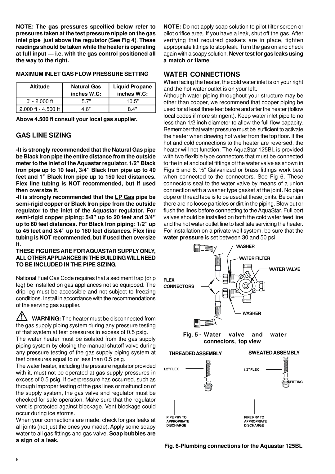
Although water piping throughout your structure may be other than copper, we recommend that copper piping be used for at least three feet before and after the heater (follow local codes if more stringent). Keep water inlet pipe to no less than 1/2 inch diameter to allow the full flow capacity. Remember that water pressure must be sufficient to activate the heater when drawing hot water from the top floor. If the hot and cold connections to the heater are reversed, the heater will not function. The AquaStar 125BL is provided with two flexible type connectors that must be connected to the inlet and outlet fittings of the water valve as shown in Figs 5 and 6. ½” Galvanized or brass fittings work best when connected to the connectors. See Fig 6. These connectors seal to the water valve by means of a union connection with a washer type gasket at the joint. No pipe dope or thread tape is to be used at these joints. Be certain there are no loose particles or dirt in the piping. Blow out or flush the lines before connecting to the AquaStar. Full port valves should be installed on both the cold water feed line and the hot water outlet line to facilitate servicing the heater. For installation on a private well system, be sure that the water pressure is set between 30 and 50 psi.

WASHER

WATER FILTER

WATER VALVE

FLEX

CONNECTORS

WASHER

Fig. 5 - Water valve and water connectors, top view

THREADEDASSEMBLY SWEATED ASSEMBLY

1/2” FLEX

1/2” FLEX

SFITTING

PIPE PRV TO

PIPE PRV TO

APPROPRIATE

APPROPRIATE

DISCHARGE

DISCHARGE

Fig. 6-Plumbing connections for the Aquastar 125BL

8

Page 8
Image 8
Bosch Appliances 125B NGL, 125B LPL GAS Line Sizing, Water Connections, Maximum Inlet GAS Flow Pressure Setting

125B NGL, 125B LPL specifications

Bosch Appliances has established itself as a leader in home innovation, offering cutting-edge products designed to enhance everyday living. Among their notable offerings are the Bosch 125B LPL and 125B NGL models, both engineered to meet the needs of modern households.

The Bosch 125B LPL features a sleek design, making it a stylish addition to any kitchen. It operates with a low noise level, allowing for an unobtrusive cooking experience. One of its standout features is the powerful performance it delivers, thanks to its innovative cooking technologies. The induction cooking system ensures rapid heating and precise temperature control, allowing users to cook their meals to perfection. The residual heat indicator is another excellent feature, ensuring safety by alerting users to hot surfaces.

On the other hand, the Bosch 125B NGL focuses on providing versatility and convenience in the kitchen. This model is equipped with advanced gas cooking technology that offers instant heat and adjustable flame control. This ensures that home chefs can simmer, sear, and sauté with precision. The integrated safety features, including a flame failure device, provide peace of mind while cooking.

Both models embody Bosch’s commitment to energy efficiency. They are designed to minimize energy consumption while maximizing performance, which is a significant advantage for environmentally conscious consumers. Additionally, the interface on both appliances is user-friendly, featuring intuitive controls that make it easy to navigate settings and cooking modes.

Bosch has also incorporated smart technology into these models, allowing users to connect their appliances with home networks for added convenience. This can include features such as remote monitoring and control, enabling homeowners to manage their cooking seamlessly.

In terms of durability, both the 125B LPL and the 125B NGL are built with high-quality materials that ensure longevity and reliability. Bosch’s reputation for fine craftsmanship is evident in every aspect, from their robust construction to the aesthetic details.

In conclusion, the Bosch Appliances 125B LPL and 125B NGL models represent the pinnacle of modern kitchen technology. With their powerful performance, energy efficiency, and user-centric features, they are perfect for those who appreciate gourmet cooking as well as everyday meal preparation. Bosch continues to redefine the culinary experience, making cooking not just a task, but an enjoyable journey.