Installation Instructions
for the
DS7433 8 Input Module
1.0General Information
The DS7433 is an 8 input Module for use with the DS7400(Xi) Series Control/Communicator. It connects directly to the DS7400(Xi) and is designed to expand it to 16 hard wired points. One DS7433 may be used per DS7400(Xi) system.
•Current Draw: 65 mA Standby. 80 mA with one point in alarm. Add 15 mA per additional point in alarm.
•Maximum Loop Impedance: 60 ohms.
•End Of Line Resistor: 2.21 K ohm.
•12 VDC Nominal Operating Voltage.
2.0Installation
Warning: | Failure to follow the mounting instructions in this |
| manual may result in damage to the DS7400(Xi) |
| Control Panel. |
Caution: | The DS7433 and DS7400(Xi) contain static sensitive |
| components and must be handled with care. Follow |
|
DS7433
9 LP+ 10 11 LP+ 12 13 LP+14 15 LP+16 |
DS7433 Front View
Printed Circuit
Stand-off “Ears” Board (PCB)
![]()
Be sure that the
• | Install the DS7433 board prior to installing the DS7400(Xi) board |
| into the control enclosure. If the DS7400(Xi) board is already |
| installed in the control panel enclosure, remove the 7400(Xi) board |
| this time. |
• | Place the DS7400(Xi) board on a flat surface with the component |
| side of the module facing up. |
A/CPower Indication LED
| 1 |
| 2 |
A | 3 |
| |
C | 4 |
| |
– | 5 |
A | 6 |
– | 7 |
+ | 8 |
Install DS7433 Here
• | Install the four plastic standoffs in the holes provided in the |
| DS7400(Xi) module. Avoid bending or flexing the DS7400(Xi) board |
| when inserting the standoffs. Be sure the standoff tabs are aligned |
| so that they do not touch any components on the module. Be sure |
| that the standoffs are firmly pressed into the board so that the |
| “ears” can expand out. See drawings. |
• | Install the DS7433 board onto the standoffs, noting that the |
| connector pins from the DS7400(Xi) are properly aligned to install |
| into the connector on the DS7433. Avoid bending or flexing the |
| boards while pressing them onto the standoffs. |
• | The DS7400(Xi) control board may be installed into the control |
| panel enclosure at this time. |
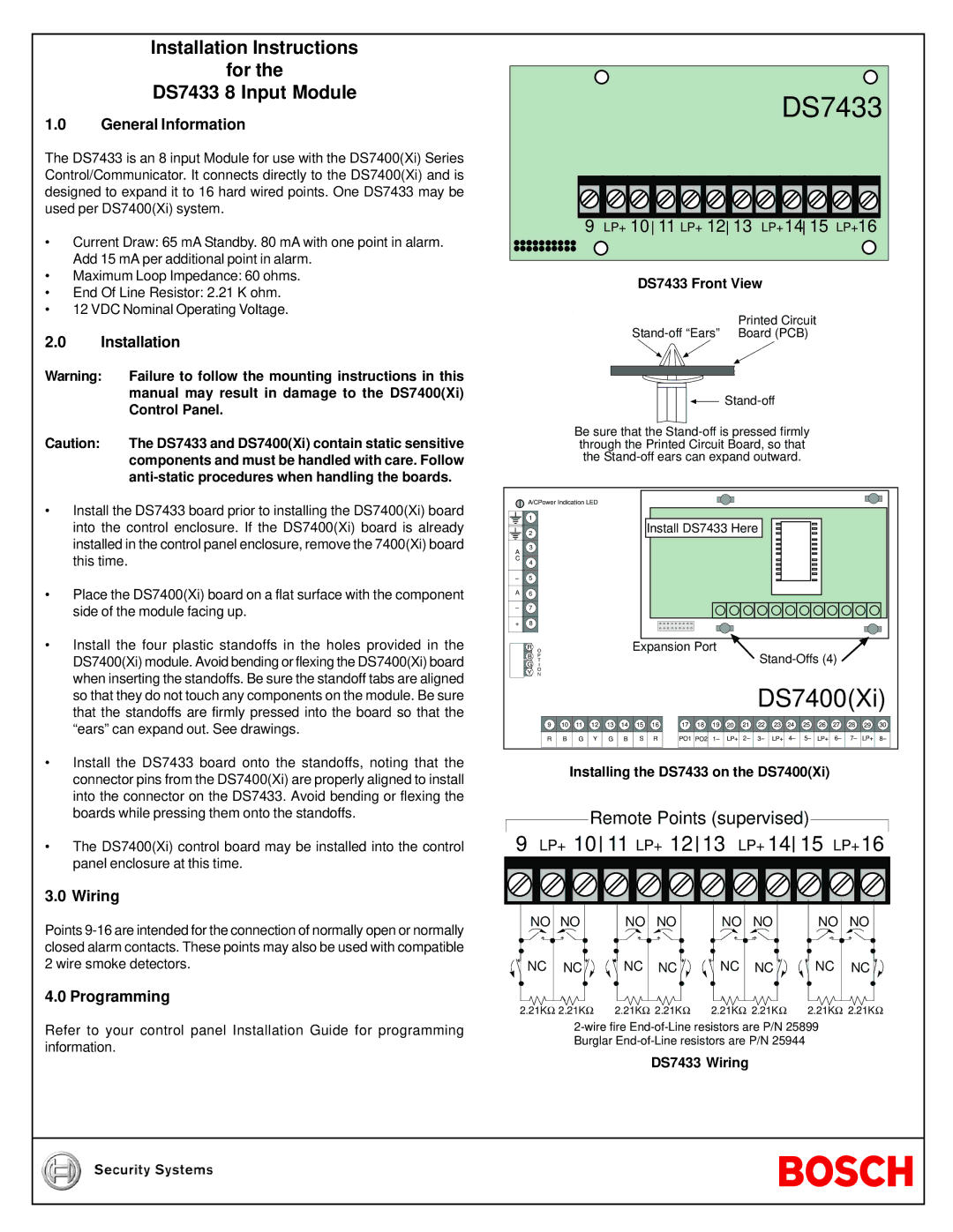
3.0 Wiring
Points
4.0 Programming
Refer to your control panel Installation Guide for programming information.
R | O |
|
|
|
|
| Expansion Port |
|
|
|
|
| ||||||||||
B | P |
|
|
|
|
|
|
|
|
|
|
|
|
|
|
| ||||||
G | I |
|
|
|
|
|
|
|
|
|
|
|
|
|
|
| ||||||
| T |
|
|
|
|
|
|
|
|
|
|
|
|
|
|
|
|
|
|
|
|
|
Y | ON |
|
|
|
|
|
|
|
|
|
|
|
|
|
|
|
|
|
|
|
|
|
|
|
|
|
|
|
|
|
|
|
|
|
|
| DS7400(Xi) | ||||||||
| 9 | 10 | 11 | 12 | 13 | 14 | 15 | 16 | 17 | 18 | 19 | 20 | 21 | 22 | 23 | 24 | 25 | 26 | 27 | 28 | 29 | 30 |
| R | B | G | Y | G | B | S | R | PO1 PO2 | 1– | LP+ | 2– | 3– | LP+ | 4– | 5– | LP+ | 6– | 7– | LP+ | 8– | |
Installing the DS7433 on the DS7400(Xi)
Remote Points (supervised)
9 LP+ 10 11 LP+ 12 13 LP+ 14 15 LP+16 | ||||||
NO NO | NO | NO | NO | NO | NO | NO |
NC NC | NC | NC | NC | NC | NC | NC |
2.21KΩ 2.21KΩ | 2.21KΩ 2.21KΩ | 2.21KΩ 2.21KΩ | 2.21KΩ 2.21KΩ | |||