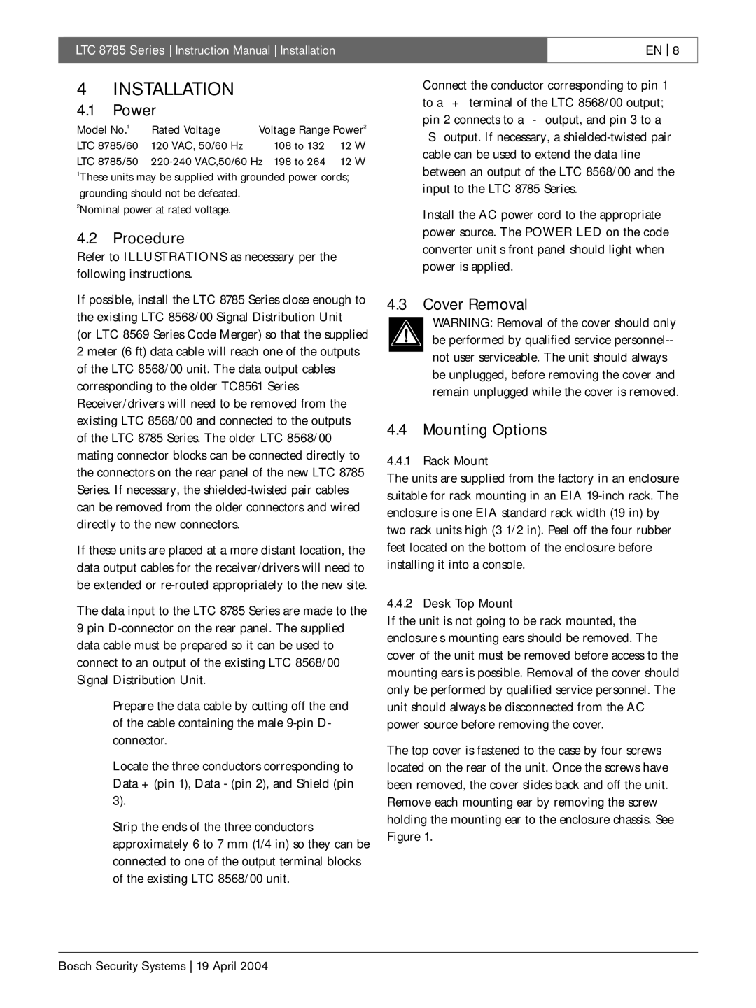
LTC 8785 specifications
The Bosch Appliances LTC 8785 is an innovative and high-performance appliance designed to enhance the modern kitchen experience. As part of Bosch's commitment to quality and efficiency, this model incorporates a range of features and technologies that make it a standout choice for discerning users.One of the key features of the LTC 8785 is its advanced cooling system. Equipped with a state-of-the-art MultiAirFlow technology, the refrigerator ensures consistent temperatures throughout the unit. This technology works by using multiple airflow vents to distribute cold air evenly, preventing temperature fluctuations that can compromise food freshness. Additionally, the fridge features a NoFrost system, which eliminates the need for manual defrosting by preventing ice buildup.
Another remarkable characteristic of the LTC 8785 is its energy efficiency. It is designed with an EcoMode, which optimizes the appliance’s performance, ensuring that it consumes less energy during non-peak hours—helping homeowners to save on utility bills while also being environmentally friendly. The appliance carries an impressive energy rating, highlighting Bosch’s dedication to sustainability and power conservation.
In terms of usability, the Bosch LTC 8785 boasts an intuitive and user-friendly interface. The bright LED lighting not only illuminates the interior but also provides a modern aesthetic. The fridge includes adjustable shelves that can easily accommodate various sizes of groceries and eliminate wasted space. Furthermore, the door storage is thoughtfully designed to maintain organization, with compartments specifically tailored for bottles and condiments.
For those who enjoy gourmet cooking, the LTC 8785 caters to culinary enthusiasts with its dedicated cooling compartments. The crisper drawers are specially designed to maintain optimal humidity levels, perfect for storing fruits and vegetables. Additionally, the appliance supports a SuperCool function that allows for rapid cooling of newly added groceries to maintain freshness.
Moreover, Bosch incorporates smart technology into the LTC 8785—enabling connectivity with smart home systems. This feature allows users to monitor and control the appliance remotely through their smartphones, providing convenience at their fingertips.
In conclusion, the Bosch Appliances LTC 8785 is a premium cooling solution that combines cutting-edge technology, energy efficiency, and user-friendly design. Its sophisticated features cater to a wide array of needs, making it an excellent choice for any modern kitchen setup.

