Assembly
CHIP EXTRACTION
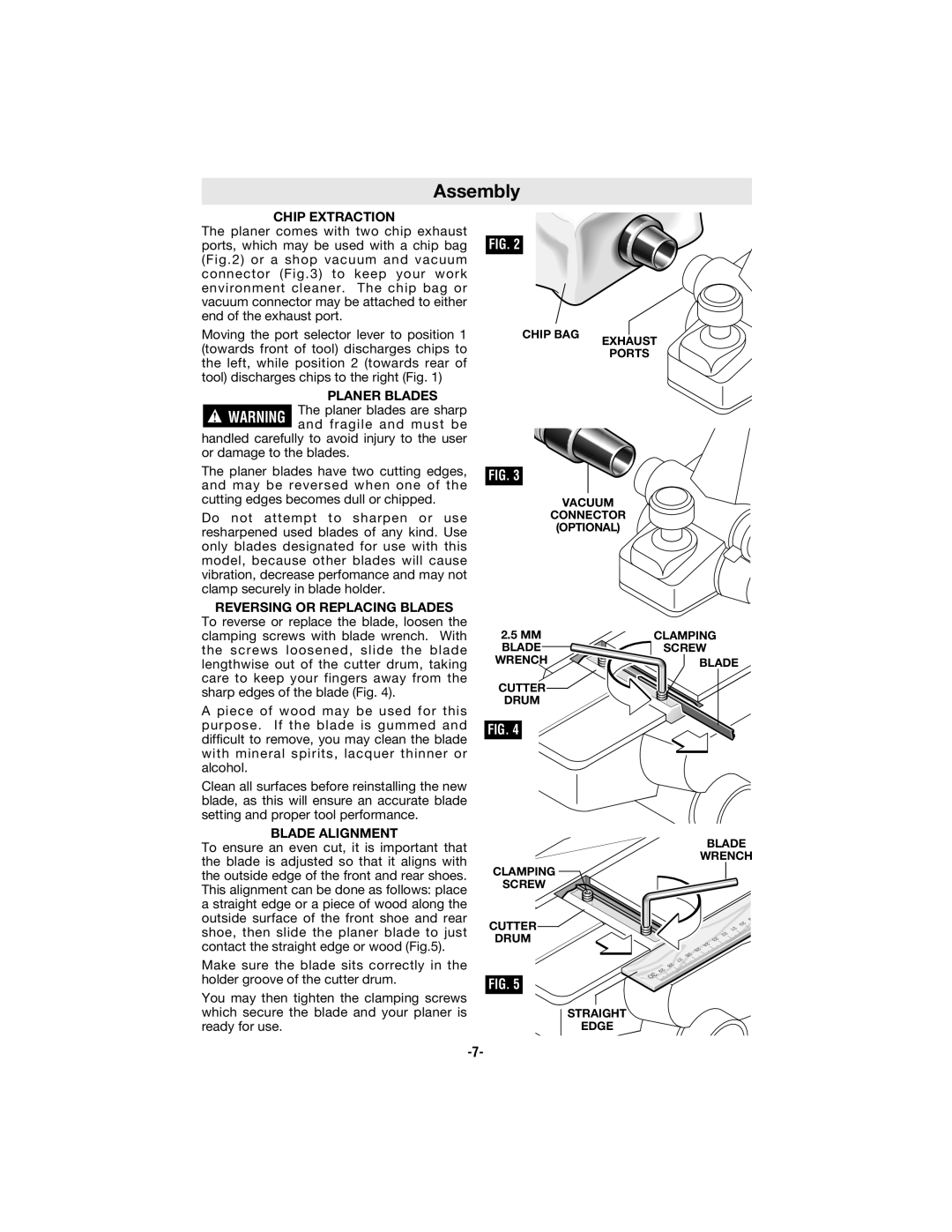
The planer comes with two chip exhaust ports, which may be used with a chip bag (Fig.2) or a shop vacuum and vacuum connector (Fig.3) to keep your work environment cleaner. The chip bag or vacuum connector may be attached to either end of the exhaust port.
Moving the port selector lever to position 1 (towards front of tool) discharges chips to the left, while position 2 (towards rear of tool) discharges chips to the right (Fig. 1)
PLANER BLADES
The planer blades are sharp ! WARNING and fragile and must be
handled carefully to avoid injury to the user or damage to the blades.
The planer blades have two cutting edges, and may be reversed when one of the
FIG. 2
CHIP BAG
FIG. 3
EXHAUST
PORTS
cutting edges becomes dull or chipped.
Do not attempt to sharpen or use resharpened used blades of any kind. Use only blades designated for use with this model, because other blades will cause vibration, decrease perfomance and may not clamp securely in blade holder.
REVERSING OR REPLACING BLADES
VACUUM
CONNECTOR
(OPTIONAL)
To reverse or replace the blade, loosen the clamping screws with blade wrench. With the screws loosened, slide the blade lengthwise out of the cutter drum, taking care to keep your fingers away from the sharp edges of the blade (Fig. 4).
A piece of wood may be used for this purpose. If the blade is gummed and difficult to remove, you may clean the blade with mineral spirits, lacquer thinner or alcohol.
Clean all surfaces before reinstalling the new blade, as this will ensure an accurate blade setting and proper tool performance.
BLADE ALIGNMENT
To ensure an even cut, it is important that the blade is adjusted so that it aligns with the outside edge of the front and rear shoes. This alignment can be done as follows: place a straight edge or a piece of wood along the outside surface of the front shoe and rear shoe, then slide the planer blade to just contact the straight edge or wood (Fig.5).
2.5MM BLADE
WRENCH
CUTTER![]()
DRUM
FIG. 4
CLAMPING
SCREW
CUTTER
DRUM
CLAMPING
SCREW ![]()
![]()
![]() BLADE
BLADE
BLADE
WRENCH
Make sure the blade sits correctly in the holder groove of the cutter drum.
You may then tighten the clamping screws which secure the blade and your planer is ready for use.
FIG. 5
STRAIGHT
EDGE