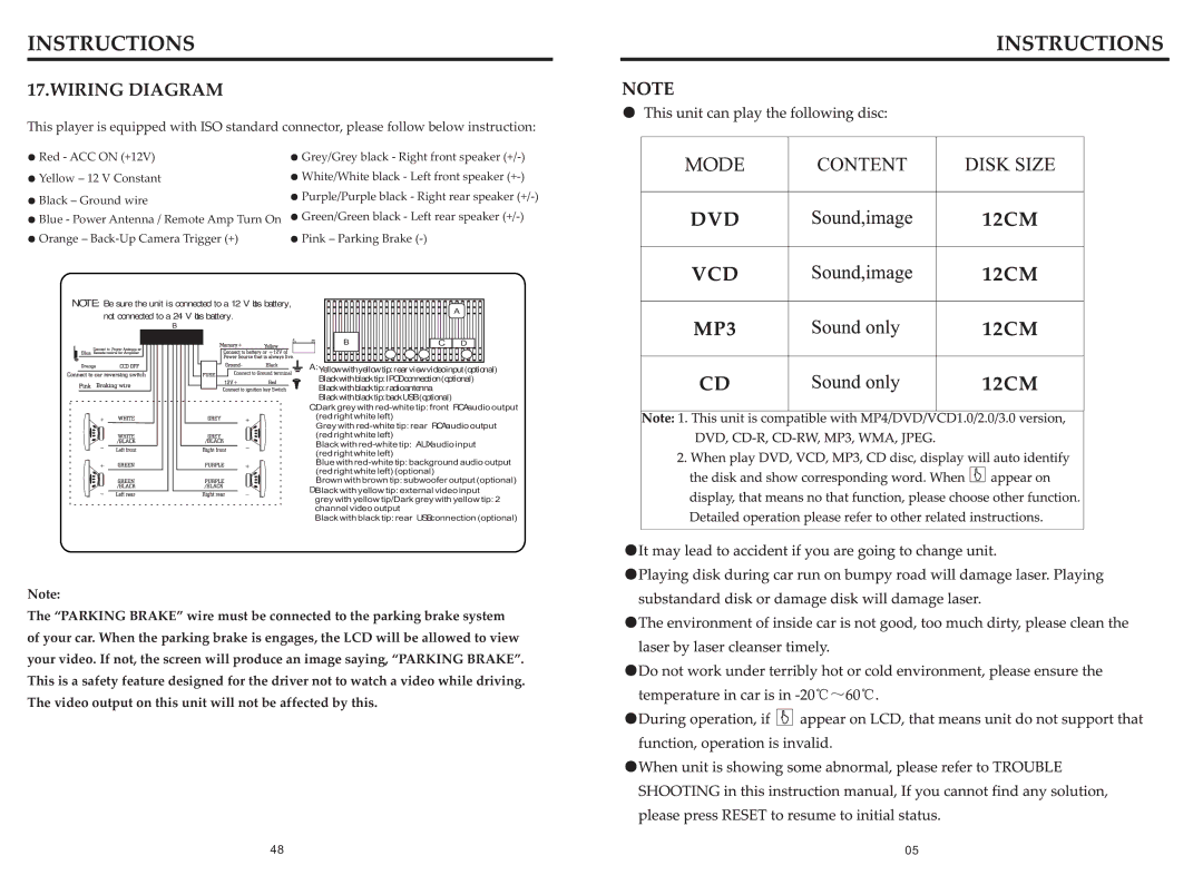
17.WIRING DIAGRAM
This player is equipped with ISO standard connector, please follow below instruction:
●Red - ACC ON (+12V)
●Yellow – 12 V Constant
●Black – Ground wire
●Blue - Power Antenna / Remote Amp Turn On
●Orange –
●Grey/Grey black - Right front speaker
●White/White black - Left front speaker
●Purple/Purple black - Right rear speaker
●Green/Green black - Left rear speaker
●Pink – Parking Brake
NOTE: Be sure the unit is connected to a 12 Volts battery,
not connected to a 24 Volts battery.
B |
![]()
![]()
![]()
![]()
![]()
![]()
![]()
![]()
![]()
![]()
![]()
![]()
![]()
![]()
![]()
![]()
![]() A
A![]()
![]()
![]()
![]()
B |
|
|
|
| C | D | |
|
|
|
|
A: Yellow with yellow tip: rear view video input (optional) Black with black tip: IPOD connection (optional)
Black with black tip: radio antenna
Black with black tip: back USB (optional)
C:Dark grey with
Grey with
Black with
Blue with
Brown with brown tip: subwoofer output (optional)
D:Black with yellow tip: external video input
grey with yellow tip/Dark grey with yellow tip: 2 channel video output
Black with black tip: rear USB connection (optional)
Note:
The “PARKING BRAKE” wire must be connected to the parking brake system
of your car. When the parking brake is engages, the LCD will be allowed to view
your video. If not, the screen will produce an image saying, “PARKING BRAKE”.
This is a safety feature designed for the driver not to watch a video while driving.
The video output on this unit will not be affected by this.
48 | 05 |
