
BV9557 specifications
The Boss Audio Systems BV9557 is a feature-rich multimedia car stereo designed to enhance the driving experience through superior audio performance and convenient connectivity options. This double DIN unit boasts a sleek and modern design, which integrates seamlessly into various vehicle interiors, making it a popular choice among car enthusiasts.At the heart of the BV9557 is its 6.5-inch touchscreen display, which provides a user-friendly interface for navigating various audio and video sources. The TFT LCD screen is responsive and bright, ensuring clear visibility under different lighting conditions. The intuitive menu layout allows users to access their favorite features with ease, making it simple to switch between music, navigation, and video playback.
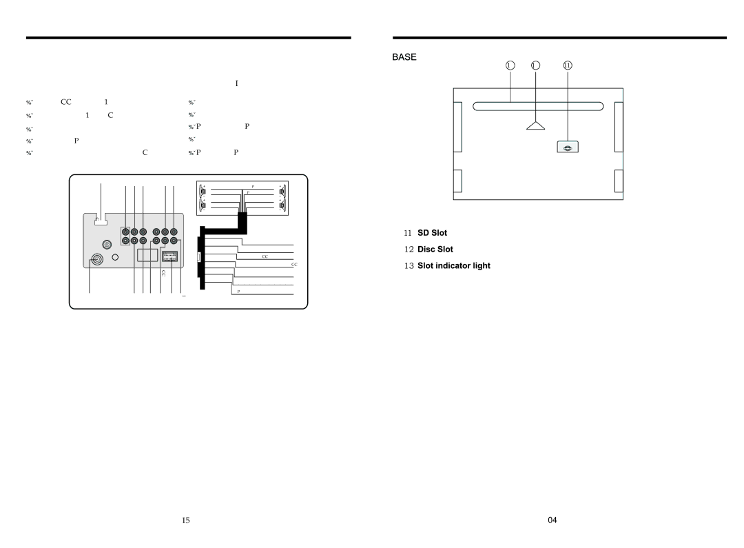
One of the standout features of the Boss BV9557 is its extensive compatibility with multiple media formats. It supports MP3, WMA, and WAV audio files, alongside a range of video formats such as AVI, MP4, and MKV. This flexibility enables users to enjoy a diverse library of content, whether through USB, SD card, or auxiliary inputs. Additionally, the stereo features Bluetooth connectivity, allowing for hands-free calling and wireless music streaming from smartphones, ensuring safety and convenience on the road.
Moreover, the Boss BV9557 is designed with enhanced sound quality in mind. It includes a built-in 3-channel amplifier, which delivers impressive audio clarity and output power. With a range of adjustable sound settings, including treble, bass, and balance controls, users can customize their listening experience to suit personal preferences and their vehicle's acoustics.
The unit also features a rear backup camera input, providing an additional layer of safety while reversing. This functionality, combined with its touchscreen interface, ensures that drivers can easily monitor their surroundings.
Another notable characteristic is the customizable LED lighting, which allows users to match the display colors with their vehicle’s interior or personal style. The Boss BV9557 is also compatible with steering wheel controls, offering added convenience without the need to take hands off the wheel.
In summary, the Boss Audio Systems BV9557 is a versatile and user-friendly multimedia car stereo that combines cutting-edge technology with robust audio capabilities. Its combination of connectivity options, exceptional sound quality, and safety features makes it an excellent choice for anyone looking to upgrade their vehicle's audio system. Whether taking a long road trip or commuting, the BV9557 ensures an enjoyable and entertaining ride.