Briggs & Stratton Power Products Automatic Transfer Switch
Installation and Owner’s Manual
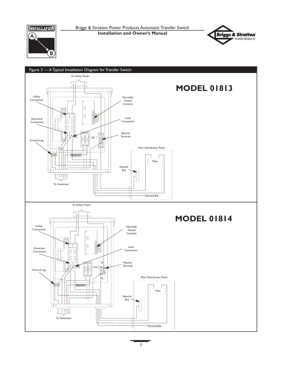
Figure 3 — A Typical Installation Diagram for Transfer Switch
| To Utility Power | |
| MODEL 01813 | |
Utility | Normally | |
Connection | Closed | |
| Contacts | |
Generator | Load | |
Connection | Connection | |
| Neutral | |
| Terminal | |
Ground Lug |
| |
| Main Distribution Panel | |
| Main | |
| Neutral | |
| Bus | |
| To Generator | |
| Ground Bus | |
| To Utility Power | |
| MODEL 01814 | |
Utility | Normally | |
Connection | Closed | |
| Contacts | |
Generator | Load | |
Connection | ||
Connection | ||
| ||
| Neutral | |
| Terminal | |
Ground Lug |
| |
| Main Distribution Panel | |
| Main | |
| Neutral | |
| Bus | |
| To Generator | |
| Ground Bus | |
| 7 |