Maintenance
13.When you move the blade rotation control to the DISENGAGE position, all movement will stop within five seconds. If there is movement of the belt or the blade(s) continue to rotate, engage and dis- engage the blade rotation control five minutes to remove any excess rubber from a new mower drive belt. If you need assistance, take the unit to an authorized service center.
14.If you replace the mower drive belt, move the blade drive spring to the top hole (see Figure 24).
7 | 5 | 4 |
| ||
|
| 1 |
|
| 2 |
|
| 3 |
|
| Figure 25 |
Adjust the Shift Lever
If the NEUTRAL position on the shift lever does not match neutral on the gearbox, adjust the shift lever as follows.
1.Stop the engine.
2.Disconnect the adjuster nut (2) from the shifter bracket (3) (see Figure 26).
3.Make sure the shift lever (4) is in the NEUTRAL position (see Figure 13).
1 | 2 | 3 |
|
| 4 |
| Figure 26 | |
4.Push the unit forward. Make sure the gearbox is in neutral.
5.To align the adjuster nut (2) with the hole in the shifter bracket (3), turn the adjuster nut (2).
6.Connect the adjuster nut to the shifter bracket.
7.Make sure the NEUTRAL position on the shift lever matches neutral on the gearbox.
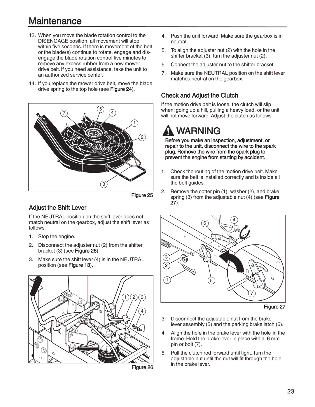
Check and Adjust the Clutch
If the motion drive belt is loose, the clutch will slip when; going up a hill, pulling a heavy load, or the unit will not move forward. Adjust the clutch as follows.
![]() WARNING
WARNING
Before you make an inspection, adjustment, or repair to the unit, disconnect the wire to the spark plug. Remove the wire from the spark plug to prevent the engine from starting by accident.
1.Check the routing of the motion drive belt. Make sure the belt is installed correctly and is inside all the belt guides.
2.Remove the cotter pin (1), washer (2), and brake spring (3) from the adjustable nut (4) (see Figure 27).
| 6 | 4 |
|
| |
3 |
|
|
2 |
|
|
1 |
| 5 |
|
| 7 |
|
| Figure 27 |
3.Disconnect the adjustable nut from the brake lever assembly (5) and the parking brake latch (6).
4.Align the hole in the brake lever with the hole in the frame. Hold the brake lever in place with a 6 mm pin or bolt (7).
5.Pull the clutch rod forward until tight. Turn the adjustable nut until the nut will fit through the hole in the brake lever.
23