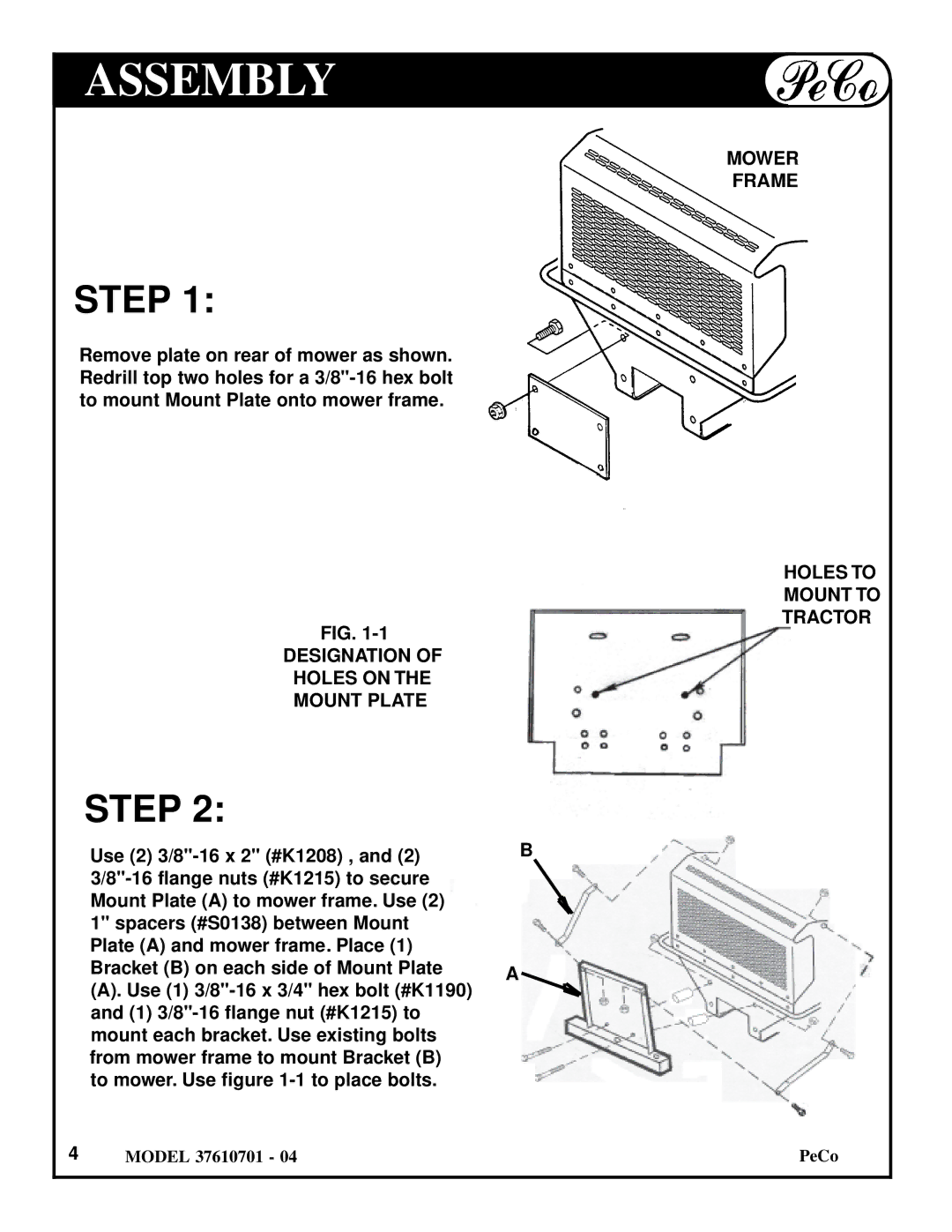
Briggs & Stratton 37610701 - 04 owner manual Assembly, Step

Models: 37610701 - 04

1 12
Download 12 pages 37.45 Kb
Page 4
Image 4
ASSEMBLY

ASSEMBLY

STEP 1:

Remove plate on rear of mower as shown. Redrill top two holes for a 3/8"-16 hex bolt to mount Mount Plate onto mower frame.

FIG. 1-1

DESIGNATION OF

HOLES ON THE

MOUNT PLATE

STEP 2:

Use (2) 3/8"-16 x 2" (#K1208) , and (2) 3/8"-16 flange nuts (#K1215) to secure Mount Plate (A) to mower frame. Use (2) 1" spacers (#S0138) between Mount Plate (A) and mower frame. Place (1) Bracket (B) on each side of Mount Plate

(A). Use (1) 3/8"-16 x 3/4" hex bolt (#K1190) and (1) 3/8"-16 flange nut (#K1215) to mount each bracket. Use existing bolts from mower frame to mount Bracket (B) to mower. Use figure 1-1 to place bolts.

4MODEL 37610701 - 04

B

A

MOWER

FRAME

HOLES TO

MOUNT TO

TRACTOR

PeCo

Page 4
Image 4
Briggs & Stratton 37610701 - 04 owner manual Assembly, Step