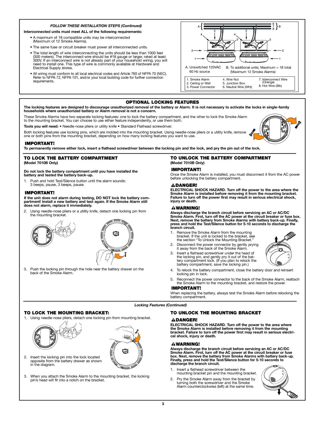
FOLLOW THESE INSTALLATION STEPS (Continued)

Interconnected units must meet ALL of the following requirements:

A maximum of 18 compatible units may be interconnected (Maximum of 12 Smoke Alarms).

The same fuse or circuit breaker must power all interconnected units.

The total length of wire interconnecting the units should be less than 1000 feet (300 meters). The interconnect wire should be #18 gauge or larger, rated at least 300V. If an interconnect wire is not already part of your household wiring, you will need to install one. This type of wire is commonly available at Hardware and Electrical Supply stores.

All wiring must conform to all local electrical codes and Article 760 of NFPA 70 (NEC). Refer to NFPA 72, NFPA 101, and/or your local building code for further connection requirements.

2 A}4

5

4

3

5

3

6

87} B2

1


1

A. Unswitched 120VAC B. To additional units; Maximum = 18 total


60 Hz source


(Maximum 12 Smoke Alarms)


1.

Smoke Alarm

4.

Wire Nut

7.

Interconnect Wire

2.

Ceiling or Wall

5.

Junction Box


(Orange)

8.

Hot Wire (Blk)

3. Power Connector

6. Neutral Wire (Wht)


OPTIONAL LOCKING FEATURES

The locking features are designed to discourage unauthorized removal of the battery or Alarm. It is not necessary to activate the locks in single-family households where unauthorized battery or Alarm removal is not a concern.

These Smoke Alarms have two separate locking features: one to lock the battery compartment, and the other to lock the Smoke Alarm to the mounting bracket. You can choose to use either feature independently, or use them both.

Tools you will need: Needle-nose pliers or utility knife • Standard Flathead screwdriver.

Both locking features use locking pins, which are molded into the mounting bracket. Using needle-nose pliers or a utility knife, remove one or both pins from the mounting bracket, depending on how many locking features you want to use.

To permanently remove either lock, insert a flathead screwdriver between the locking pin and the lock, and pry the pin out of the lock.

TO LOCK THE BATTERY COMPARTMENT

(Model 7010B Only)

Do not lock the battery compartment until you have installed the battery and tested the battery back-up.

1.Push and hold Test/Silence button until the alarm sounds: 3 beeps, pause, 3 beeps, pause.

If the unit does not alarm during testing, DO NOT lock the battery com- partment! Install a new battery and test again. If the Smoke Alarm still does not alarm, replace it immediately.

2.Using needle-nose pliers or a utility knife, detach one locking pin from the mounting bracket.

3.Push the locking pin through the hole near the battery drawer on the back of the Smoke Alarm.

TO UNLOCK THE BATTERY COMPARTMENT

(Model 7010B Only)

Once the Smoke Alarm is installed, you must disconnect it from the AC power before unlocking the battery compartment.

ELECTRICAL SHOCK HAZARD. Turn off the power to the area where the Smoke Alarm is installed before removing it from the mounting bracket. Failure to turn off the power first may result in serious electrical shock, injury or death.

Always discharge the branch circuit before servicing an AC or AC/DC Smoke Alarm. First, turn off the AC power at the circuit breaker or fuse box. Next, remove the battery from Smoke Alarms with battery back-up. Finally, press and hold the Test/Silence button for 5-10 seconds to discharge the branch circuit.

1. Remove the Smoke Alarm from the mounting bracket. If the unit is locked to the bracket, see the section “To Unlock the Mounting Bracket.”

2. Disconnect the power connector by gently prying it away from the back of the Smoke Alarm.

3. Insert a flathead screwdriver under the head of the locking pin, and gently pry it out of the bat- tery compartment lock. (If you plan to relock the battery compartment, save the locking pin.)

4.To relock the battery compartment, close the battery door and reinsert locking pin in lock.

5.Reconnect the power connector to the back of the Smoke Alarm, reattach the Smoke Alarm to the mounting bracket, and restore the power.

When replacing the battery, always test the Smoke Alarm before relocking the battery compartment.

Locking Features (Continued)

TO LOCK THE MOUNTING BRACKET:

1. Using needle-nose pliers, detach one locking pin from mounting bracket.

2.Insert the locking pin into the lock located opposite from the battery drawer as shown in the diagram.

3.When you attach the Smoke Alarm to the mounting bracket, the locking pin’s head will fit into a notch on the bracket.

TO UNLOCK THE MOUNTING BRACKET

ELECTRICAL SHOCK HAZARD. Turn off the power to the area where the Smoke Alarm is installed before removing it from the mounting bracket. Failure to turn off the power first may result in serious electri- cal shock, injury or death.

Always discharge the branch circuit before servicing an AC or AC/DC Smoke Alarm. First, turn off the AC power at the circuit breaker or fuse box. Next, remove the battery from Smoke Alarms with battery back-up. Finally, press and hold the Test/Silence button for 5-10 seconds to discharge the branch circuit.

1. Insert a flathead screwdriver between the mounting bracket pin and the mounting bracket.

2. Pry the Smoke Alarm away from the bracket by turning both the screwdriver and the Smoke Alarm counterclockwise (left) at the same time.

3

Page 3
Image 3
BRK electronic 7010B Optional Locking Features, To Lock the Battery Compartment, To Unlock the Battery Compartment

7010B, 7010 specifications

The BRK Electronic 7010B and 7010 are state-of-the-art smoke alarms designed to enhance safety and ensure peace of mind in residential and commercial buildings. These models blend innovative technology with user-friendly features, making them a preferred choice for many users.

One of the key characteristics of the BRK Electronic 7010B and 7010 is their advanced photoelectric sensing technology, which is particularly effective in detecting smoldering fires that produce a significant amount of smoke without an open flame. This type of sensor reduces false alarms, which can be triggered by steam or cooking smoke, thus allowing users to maintain peace in their homes without frequent disturbances.

The 7010B features a 10-year sealed battery, providing long-term reliability without the hassle of battery replacement. This built-in battery ensures that the unit remains functional over the typical lifespan of the alarm, providing continuous protection for a decade. Additionally, the battery seal prevents tampering, eliminating the risk of users removing the battery to silence unwanted alarms.

Equipped with a loud 85-decibel alarm, both models are designed to alert occupants promptly in the event of smoke detection. The alarm is powerful enough to wake sleeping individuals, which is crucial during nighttime emergencies. Complementing the audible alarm is a visual indicator, often featuring a bright LED that flashes to provide a clear visual alert of smoke detection.

Another notable feature of the BRK Electronic 7010B and 7010 is the integrated test/silence button. This button allows users to easily test the functionality of the alarm or silence the unit in the event of a non-threatening situation. This feature enhances user control and fosters a proactive approach to fire safety.

The units are also designed for easy installation, with a simple mounting bracket that allows for quick setup in any environment. Additionally, the 7010B and 7010 comply with various safety standards, reinforcing their reliability and effectiveness in smoke detection.

In summary, the BRK Electronic 7010B and 7010 smoke alarms stand out due to their advanced photoelectric technology, 10-year sealed battery, powerful alarm sound, and user-friendly features. These characteristics make them an excellent choice for anyone looking to enhance their fire safety measures while benefiting from a reliable and efficient smoke detection system.