
676, 684 specifications
The Broan 676 and 684 range hoods are essential additions to modern kitchens, marrying functionality with sleek design. These range hoods are engineered to enhance ventilation, eliminate odors, and improve air quality, all while complementing contemporary kitchen aesthetics.One of the key features of both models is their powerful ventilation system. The Broan 676 and 684 are equipped with robust motors that deliver efficient airflow, allowing for the effective expulsion of smoke, steam, and cooking odors. The adjustable fan speeds provide versatility, enabling users to customize airflow to suit their cooking needs, whether they’re simmering sauces or searing meats.
In terms of design, both models showcase a streamlined look that seamlessly fits into various kitchen décors. Available in multiple finishes, including stainless steel, they offer a professional touch while ensuring durability and easy maintenance. The compact design also maximizes space, making them ideal for kitchens of all sizes.
Technologically, the Broan 676 and 684 feature easy-to-use controls that allow for quick adjustments. Many users appreciate the inclusion of variable speed settings, which provide enhanced control over the extraction power. The integrated lighting is another highlight; it offers bright, efficient illumination over the cooking area, making it easier to monitor food as it cooks.
Noise levels are often a concern with range hoods, but both the Broan 676 and 684 operate quietly, ensuring a peaceful cooking environment. The engineers at Broan have focused on sound reduction features, allowing for ventilation without the typical noise associated with range hoods.
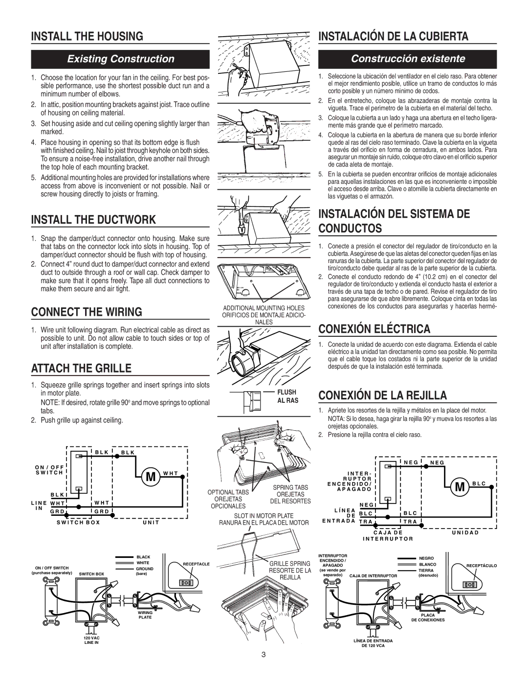
Installation of the Broan range hoods is straightforward, with a comprehensive mounting system that allows for different configurations, whether for under-cabinet, wall-mounted, or ducted applications. This flexibility ensures that homeowners have options suitable for their specific kitchen layouts.
Overall, the Broan 676 and 684 range hoods epitomize a blend of performance, style, and convenience. Their powerful ventilation capabilities, stylish designs, advanced technology, and user-friendly features make them excellent choices for anyone looking to enhance their cooking experience while maintaining a fresh and clean kitchen environment.