Local Management Console
An
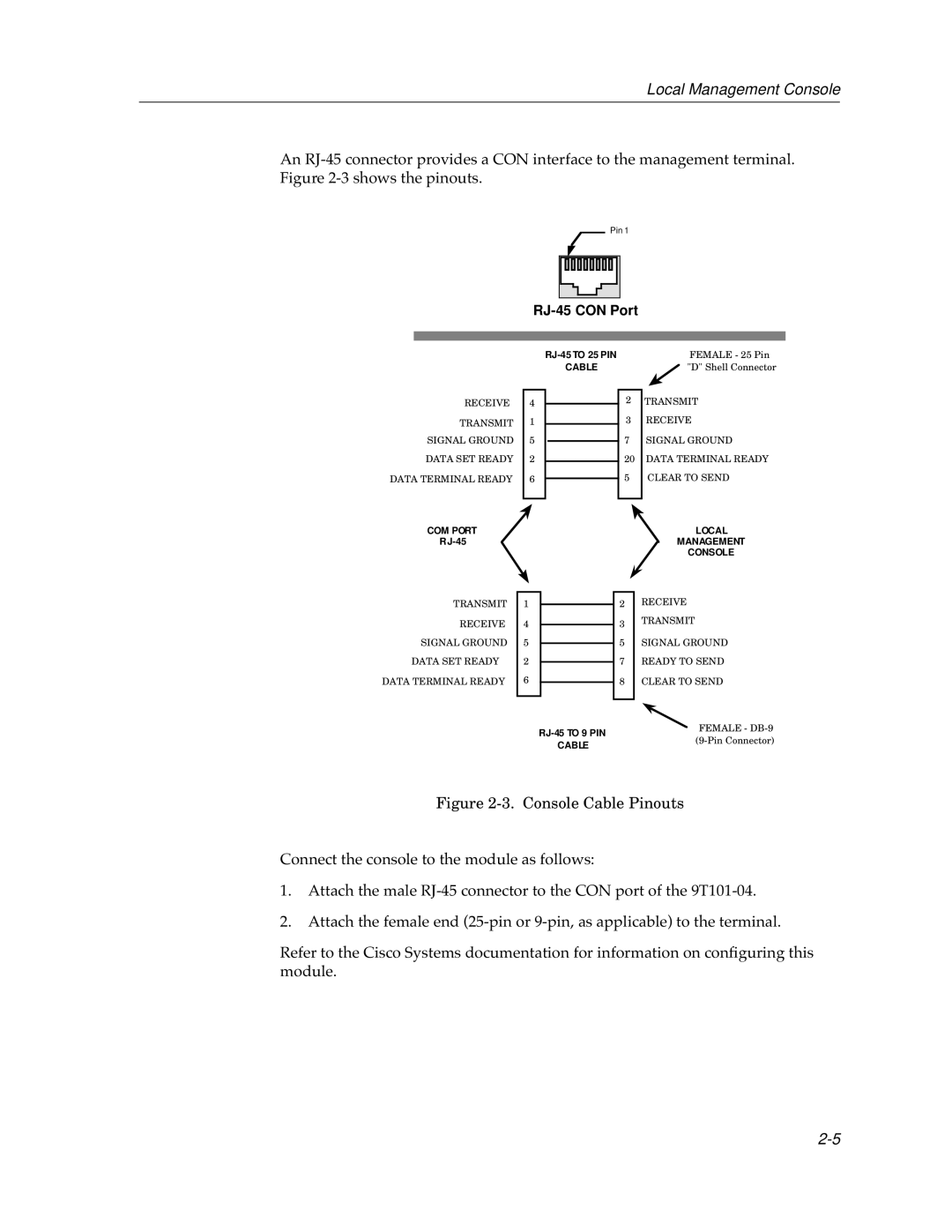
![]() Pin 1
Pin 1
RJ-45 CON Port
RJ-45 COM PORT
RECEIVE | 4 |
TRANSMIT | 1 |
SIGNAL GROUND | 5 |
DATA SET READY | 2 |
DATA TERMINAL READY | 6 |
|
|
FEMALE - 25 Pin | ||
CABLE | "D" Shell Connector | |
|
|
|
| 2 | TRANSMIT |
| 3 | RECEIVE |
| 7 | SIGNAL GROUND |
| 20 | DATA TERMINAL READY |
| 5 | CLEAR TO SEND |
|
|
|
COM PORT |
|
|
| LOCAL |
|
|
| MANAGEMENT | |
|
|
|
| CONSOLE |
|
|
|
| RECEIVE |
TRANSMIT | 1 |
| 2 | |
RECEIVE | 4 |
| 3 | TRANSMIT |
|
| |||
SIGNAL GROUND | 5 |
| 5 | SIGNAL GROUND |
DATA SET READY | 2 |
| 7 | READY TO SEND |
DATA TERMINAL READY | 6 |
| 8 | CLEAR TO SEND |
|
|
|
|
|
|
|
|
|
|
FEMALE - | ||
CABLE | ||
|