3 INSTALLATION
3.7 Mode Selector
The switch on the rear panel changes the operating mode. Switch the power switch to the Off position to make changes on the Mode Selector. When the amplifier is switched on again, the selected mode will operate.
3.8 Wiring
3.8.1 E.U.I. and XLR Connection
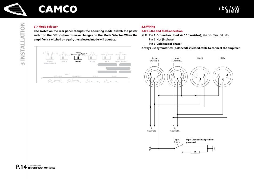
XLR: Pin 1 = Ground (or lifted via 15 Ω resistor) (See 3.5 Ground Lift) Pin 2 = Hot (inphase)
Pin 3 = Cold (out of phase)
Always use symmetrical (balanced) shielded cable to connect the amplifier.
| Input |
| Input | LINK B | LINK A | ||
Channel B | Channel A |
|
| ||||
|
|
|
|
|
|
|
|
|
|
|
|
|
|
|
|
2 | 1 | 2 | 1 | 1 | 2 | 1 | 2 |
| 3 |
| 3 |
| 3 |
| 3 |
P.14
USER MANUAL
TECTON POWER AMP SERIES
To![]() Channel B
Channel B
To
Channel A
Input
Ground
Lift
Input Ground Lift in position: grounded