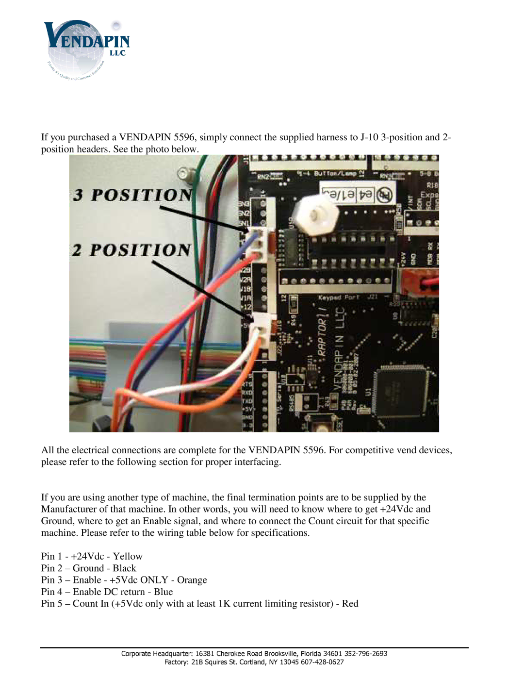
If you purchased a VENDAPIN 5596, simply connect the supplied harness to
All the electrical connections are complete for the VENDAPIN 5596. For competitive vend devices, please refer to the following section for proper interfacing.
If you are using another type of machine, the final termination points are to be supplied by the Manufacturer of that machine. In other words, you will need to know where to get +24Vdc and Ground, where to get an Enable signal, and where to connect the Count circuit for that specific machine. Please refer to the wiring table below for specifications.
Pin 1 - +24Vdc - Yellow Pin 2 – Ground - Black
Pin 3 – Enable - +5Vdc ONLY - Orange Pin 4 – Enable DC return - Blue
Pin 5 – Count In (+5Vdc only with at least 1K curre nt limiting resistor) - Red
Corporate Headquarter: 16381 Cherokee Road Brooksville, Florida 34601
Factory: 21B Squires St. Cortland, NY 13045