| TYPICAL WIRENUT |
|
|
| (WHEN REQUIRED) | WIRE CLIP |
|
|
|
| |
| BLK |
|
|
| RED OR |
|
|
EXISTING | VIO |
|
|
WIRES | WHT |
|
|
|
|
| |
| RED |
|
|
|
| RED |
|
|
| WHT | BLK |
EXISTING SURGE |
| VIO | |
|
| ||
RESISTOR |
|
|
|
BUSBAR |
|
|
|
GND
A95271
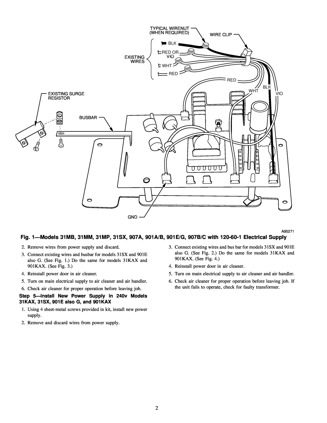
Fig. 1ÐModels 31MB, 31MM, 31MP, 31SX, 907A, 901A/B, 901E/G, 907B/C with
2.Remove wires from power supply and discard.
3.Connect existing wires and busbar for models 31SX and 901E also G. (See Fig. 1.) Do the same for models 31KAX and 901KAX. (See Fig. 3.)
4.Reinstall power door in air cleaner.
5.Turn on main electrical supply to air cleaner and air handler.
6.Check air cleaner for proper operation before leaving job.
Step 5ÐInstall New Power Supply in 240v Models 31KAX, 31SX, 901E also G, and 901KAX
1.Using 4
2.Remove and discard wires from power supply.
3.Connect existing wires and bus bar for models 31SX and 901E also G. (See Fig. 2.) Do the same for models 31KAX and 901KAX. (See Fig. 4.)
4.Reinstall power door in air cleaner.
5.Turn on main electrical supply to air cleaner and air handler.
6.Check air cleaner for proper operation before leaving job. If the unit fails to operate, check for faulty transformer.
2