REFRIGERANT TUBING — Connect tubing to fittings on out- door unit vapor and liquid service valves. (See Fig. 2 and 5.)
SWEAT CONNECTION — Use refrigerant grade tubing. Service valves are closed from factory and ready for brazing. After wrapping service valve with a wet cloth, tubing set can be brazed to service valve using either silver bearing or
Step 6—Make Electrical Connections
To avoid personal injury or death, do not supply power to unit with compressor terminal box cover removed.
Be sure field wiring complies with local and national fire, safety, and electrical codes, and voltage to system is within limits shown on unit rating plate. Contact local power company for correction of improper voltage. See unit rating plate for recommended circuit protection device.
NOTE: Operation of unit on improper line voltage constitutes abuse and could affect unit reliability. See unit rating plate. Do not install unit in system where voltage may fluctuate above or below permissible limits.
NOTE: Use copper wire only between disconnect switch and unit.
NOTE: Install branch circuit disconnect per local codes to handle unit starting current. Locate disconnect within sight from and readily accessible from unit per local codes.
ROUTE GROUND AND POWER WIRES — Remove access panel and control box cover to gain access to unit wiring. Extend wires from disconnect through power wiring hole provided and into unit control box. (See Fig. 2.) Size wires per local codes but not smaller than minimum wire size shown on unit rating plate.
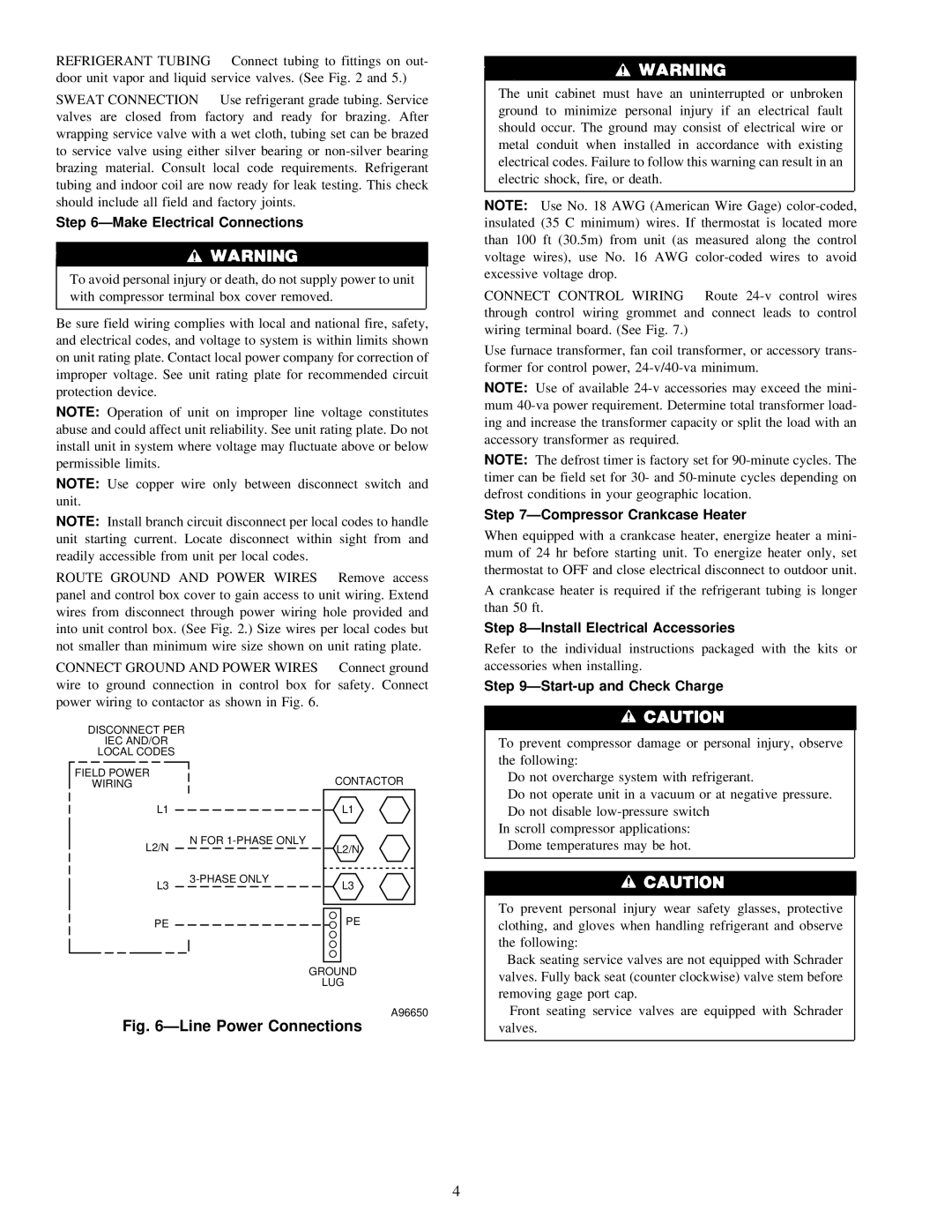
CONNECT GROUND AND POWER WIRES — Connect ground wire to ground connection in control box for safety. Connect power wiring to contactor as shown in Fig. 6.
The unit cabinet must have an uninterrupted or unbroken ground to minimize personal injury if an electrical fault should occur. The ground may consist of electrical wire or metal conduit when installed in accordance with existing electrical codes. Failure to follow this warning can result in an electric shock, fire, or death.
NOTE: Use No. 18 AWG (American Wire Gage)
CONNECT CONTROL WIRING — Route
Use furnace transformer, fan coil transformer, or accessory trans- former for control power,
NOTE: Use of available
NOTE: The defrost timer is factory set for
Step 7—Compressor Crankcase Heater
When equipped with a crankcase heater, energize heater a mini- mum of 24 hr before starting unit. To energize heater only, set thermostat to OFF and close electrical disconnect to outdoor unit.
A crankcase heater is required if the refrigerant tubing is longer than 50 ft.
Step 8—Install Electrical Accessories
Refer to the individual instructions packaged with the kits or accessories when installing.
Step 9—Start-up and Check Charge
DISCONNECT PER
IEC AND/OR
LOCAL CODES
FIELD POWER
WIRING
L1
L2/N
L3
PE
CONTACTOR
L1
N FOR
L2/N
L3
PE
GROUND
LUG
A96650
To prevent compressor damage or personal injury, observe the following:
•Do not overcharge system with refrigerant.
•Do not operate unit in a vacuum or at negative pressure.
•Do not disable
In scroll compressor applications:
• Dome temperatures may be hot.
To prevent personal injury wear safety glasses, protective clothing, and gloves when handling refrigerant and observe the following:
• Back seating service valves are not equipped with Schrader |
valves. Fully back seat (counter clockwise) valve stem before |
removing gage port cap. |
• Front seating service valves are equipped with Schrader |
Fig. 6—Line Power Connections
valves. |
4