!WARNING

FIRE AND EXPLOSION HAZARD

Failure to follow this warning could result in personal injury, death, and/or property damage.

1.If the main burners fail to light, or the blower fails to start, shut down gas heating section and call your dealer for service.

2.Never attempt to manually light the main burners on unit with a match, lighter, or any other flame. If the electric sparking device fails to light the main burners, refer to the following shutdown procedures, then call your dealer as soon as possible.

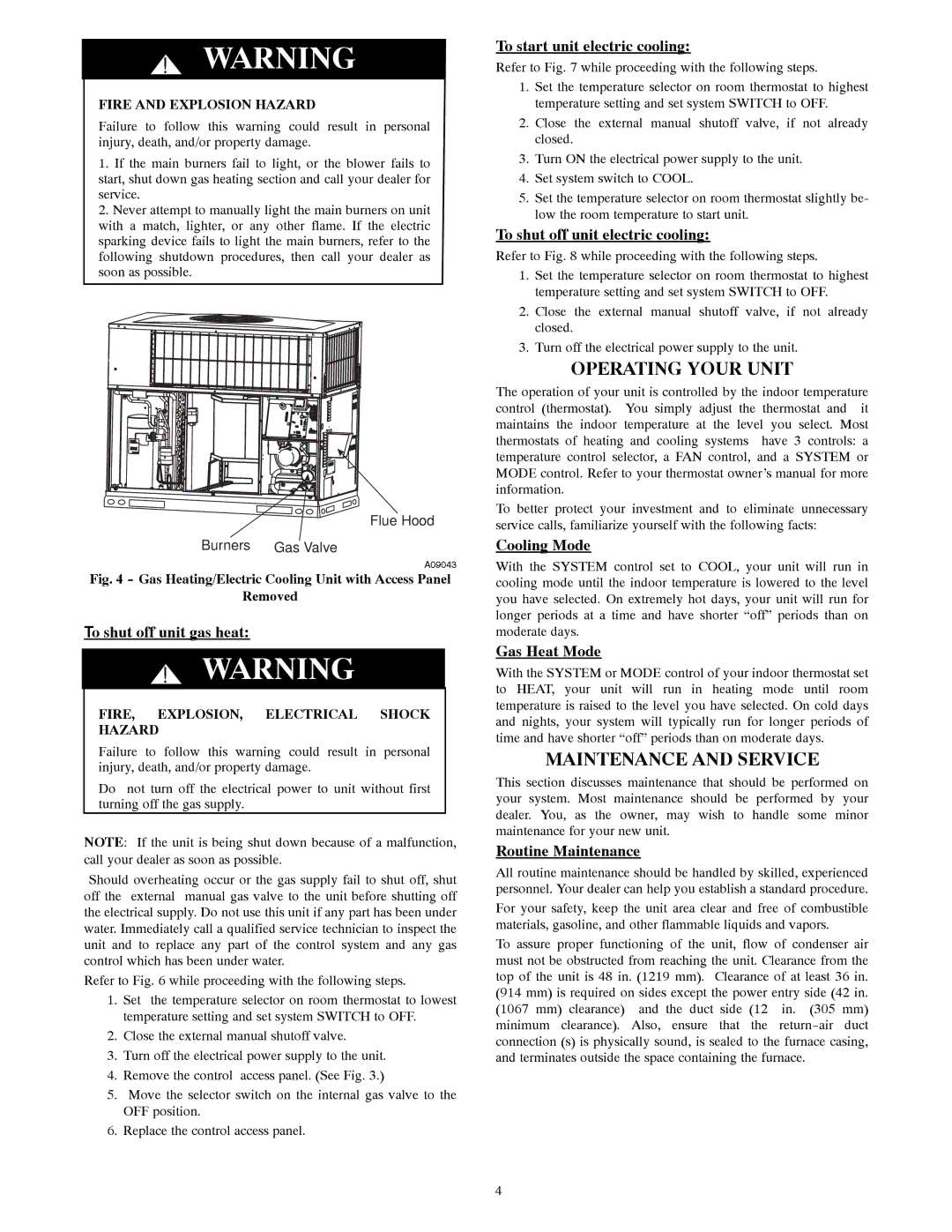
Flue Hood

Burners Gas Valve

A09043

Fig. 4 - Gas Heating/Electric Cooling Unit with Access Panel

Removed

To shut off unit gas heat:

!WARNING

FIRE, EXPLOSION, ELECTRICAL SHOCK HAZARD

Failure to follow this warning could result in personal injury, death, and/or property damage.

Do not turn off the electrical power to unit without first turning off the gas supply.

NOTE: If the unit is being shut down because of a malfunction, call your dealer as soon as possible.

Should overheating occur or the gas supply fail to shut off, shut off the external manual gas valve to the unit before shutting off the electrical supply. Do not use this unit if any part has been under water. Immediately call a qualified service technician to inspect the unit and to replace any part of the control system and any gas control which has been under water.

Refer to Fig. 6 while proceeding with the following steps.

1.Set the temperature selector on room thermostat to lowest temperature setting and set system SWITCH to OFF.

2.Close the external manual shutoff valve.

3.Turn off the electrical power supply to the unit.

4.Remove the control access panel. (See Fig. 3.)

5.Move the selector switch on the internal gas valve to the OFF position.

6.Replace the control access panel.

To start unit electric cooling:

Refer to Fig. 7 while proceeding with the following steps.

1.Set the temperature selector on room thermostat to highest temperature setting and set system SWITCH to OFF.

2.Close the external manual shutoff valve, if not already closed.

3.Turn ON the electrical power supply to the unit.

4.Set system switch to COOL.

5.Set the temperature selector on room thermostat slightly be- low the room temperature to start unit.

To shut off unit electric cooling:

Refer to Fig. 8 while proceeding with the following steps.

1.Set the temperature selector on room thermostat to highest temperature setting and set system SWITCH to OFF.

2.Close the external manual shutoff valve, if not already closed.

3.Turn off the electrical power supply to the unit.

OPERATING YOUR UNIT

The operation of your unit is controlled by the indoor temperature control (thermostat). You simply adjust the thermostat and it maintains the indoor temperature at the level you select. Most thermostats of heating and cooling systems have 3 controls: a temperature control selector, a FAN control, and a SYSTEM or MODE control. Refer to your thermostat owner’s manual for more information.

To better protect your investment and to eliminate unnecessary service calls, familiarize yourself with the following facts:

Cooling Mode

With the SYSTEM control set to COOL, your unit will run in cooling mode until the indoor temperature is lowered to the level you have selected. On extremely hot days, your unit will run for longer periods at a time and have shorter “off” periods than on moderate days.

Gas Heat Mode

With the SYSTEM or MODE control of your indoor thermostat set to HEAT, your unit will run in heating mode until room temperature is raised to the level you have selected. On cold days and nights, your system will typically run for longer periods of time and have shorter “off” periods than on moderate days.

MAINTENANCE AND SERVICE

This section discusses maintenance that should be performed on your system. Most maintenance should be performed by your dealer. You, as the owner, may wish to handle some minor maintenance for your new unit.

Routine Maintenance

All routine maintenance should be handled by skilled, experienced personnel. Your dealer can help you establish a standard procedure.

For your safety, keep the unit area clear and free of combustible materials, gasoline, and other flammable liquids and vapors.

To assure proper functioning of the unit, flow of condenser air must not be obstructed from reaching the unit. Clearance from the top of the unit is 48 in. (1219 mm). Clearance of at least 36 in. (914 mm) is required on sides except the power entry side (42 in. (1067 mm) clearance) and the duct side (12 in. (305 mm) minimum clearance). Also, ensure that the return-air duct connection (s) is physically sound, is sealed to the furnace casing, and terminates outside the space containing the furnace.

4

Page 4
Image 4
Carrier 48ES---A, 48VL-A manual Operating Your Unit, Maintenance and Service

48VL-A, 48ES---A specifications

The Carrier 48VL-A and 48ES-A series are advanced air conditioning units designed to provide exceptional performance and energy efficiency for commercial and residential applications. These systems are engineered to deliver reliable cooling and heating solutions, ensuring comfort in varied climates.

One of the standout features of the Carrier 48VL-A is its variable speed compressor technology. This innovation allows the system to adjust its cooling and heating output in response to real-time demands. By operating at lower speeds during periods of moderate cooling needs, the 48VL-A significantly reduces energy consumption. This technology not only enhances energy efficiency but also minimizes temperature fluctuations, providing a more stable indoor environment.

The 48ES-A series, on the other hand, is particularly noted for its high-efficiency ratings. These units are equipped with a sophisticated scroll compressor that is designed for durability and quiet operation. With Energy Efficiency Ratio (EER) values that exceed industry standards, the 48ES-A provides significant cost savings on energy bills while helping to reduce carbon footprints.

Both the 48VL-A and 48ES-A models incorporate advanced heat exchanger designs that optimize heat transfer and improve overall system efficiency. The use of state-of-the-art materials in the construction of these heat exchangers ensures durability and resistance to corrosion, extending the lifespan of the units.

Furthermore, the controls of the Carrier 48VL-A and 48ES-A systems are designed with user-friendliness in mind. They feature intuitive interfaces that allow for easy adjustments and programming, giving users greater control over their indoor climate. Additionally, these systems can be integrated with smart home technologies, allowing for remote monitoring and management through mobile applications.

Noise levels are kept to a minimum, making these units suitable for residential and commercial settings where quiet operation is essential. The use of sound-dampening materials and thoughtful design reduces vibration and operational sounds, enhancing user comfort.

Furthermore, both models are designed with environmental sustainability in mind. They are compatible with environmentally friendly refrigerants, aligning with Carrier's commitment to reducing environmental impact and enhancing system efficiency.

In conclusion, the Carrier 48VL-A and 48ES-A air conditioning units embody the perfect blend of efficiency, advanced technology, and user-friendly controls. With their innovative features and reliable performance, they stand out as top choices for energy-conscious consumers seeking optimal comfort solutions.