INSTALLER-SELECTABLE OPTIONS
Carefully cutting programming resistor jumpers or traces on the printed circuit board inside the case can select various options. The cover must be removed to access the jumpers. The cover is held in place by a
Auxiliary Input Function - The auxiliary input normally activates the Horn function. Do not cut the jumper resistor labeled "AUX I".
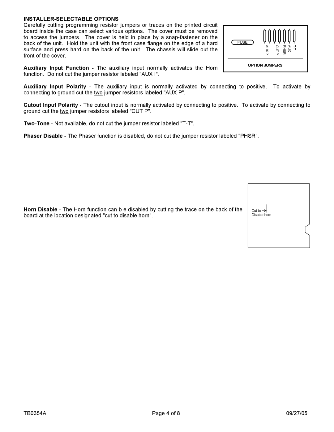
FUSE
AUX P | CUT P | |
|
|
|
OPTION JUMPERS
Auxiliary Input Polarity - The auxiliary input is normally activated by connecting to positive. To activate by connecting to ground cut the two jumper resistors labeled "AUX P".
Cutout Input Polarity - The cutout input is normally activated by connecting to positive. To activate by connecting to ground cut the two jumper resistors labeled "CUT P".
Phaser Disable - The Phaser function is disabled, do not cut the jumper resistor labeled "PHSR".
Horn Disable - The Horn function can b e disabled by cutting the trace on the back of the board at the location designated "cut to disable horn".
Cut to Disable horn
TB0354A | Page 4 of 8 | 09/27/05 |