OPERATION
Each pushbutton switch on the face of the unit controls a corresponding output on the back. The pushbutton switch is push on/push off operation. When pushed on, the legend above the switch will light red and +VDC is supplied to corresponding output. The units backlighting may be connected to vehicles accessory panel. See OPTION SWITCHES below for further operational enhancements.
If the internal fuse ruptures the output will automatically
INSTALLATION
Proper installation of the unit is essential for years of safe, reliable operation. Please read all instruction before installing the unit. Failure to follow these instructions can cause serious damage to the unit or vehicle and may void warranties.
SAFETY PRECAUTIONS
For the safety of the installer, vehicle operator, passengers and the community please observe the following safety precautions.
Failure to follow all safety precautions and instructions may result in property damage, injury or death.
Qualifications - The installer must have a firm knowledge of basic electricity, vehicle electrical systems, and emergency equipment. Mounting - Mount the control box for easy access by the vehicle operator. DO NOT mount in air bag deployment area. Assure clearances before drilling in vehicle. To prevent internal damage to the unit, mounting bolts must not enter case more than 1/4".
Wiring - Use wiring capable of handling the current required. Make sure all connections are tight. Route wiring to prevent wear, overheating and interference with air bag deployment. Install and check all wiring before connection to vehicle battery.
Testing - Test all functions after installation to assure proper operation.
UNPACKING
Inspect contents for shipping damage. If found alert carrier immediately. Contents should include switch control box, mounting bracket and 2 bolts, two power input cables, two power output cables, backlight and grounding cable, sheet of legends, and these instructions. Contact supplier immediately if any components are missing.
OPTION SWITCHES
Remove cover (single screw on back) to gain access to option switches inside the unit.
Combo option switch (behind switch 1) combines output 1 and 2 to be activated by switch 1 or 2.
Momentary option switch (behind switch 8) sets switch 8 for momentary operation. Output 8 will activate for 10 seconds then
LEGENDS
Multiple legends are supplied on a single sheet. Legends may be selected to match the device controlled.
Select the legend and place centered over the legend area. Press down on the legend to stick over clear window and tuck under rubber framing. Gently lift up on the sides of rubber framing to help cover the edges of the legend.
To remove a legend, use a thin edge to gently push rubber frame aside and pry between legend and clear window. Try not to puncture clear window. The
Blank (black) legends are provided for switches with no function. The white background legends may be written on with permanent marker to create custom legends.
Legend
Area
1
Legend Label
Rubber Frame Clear Window
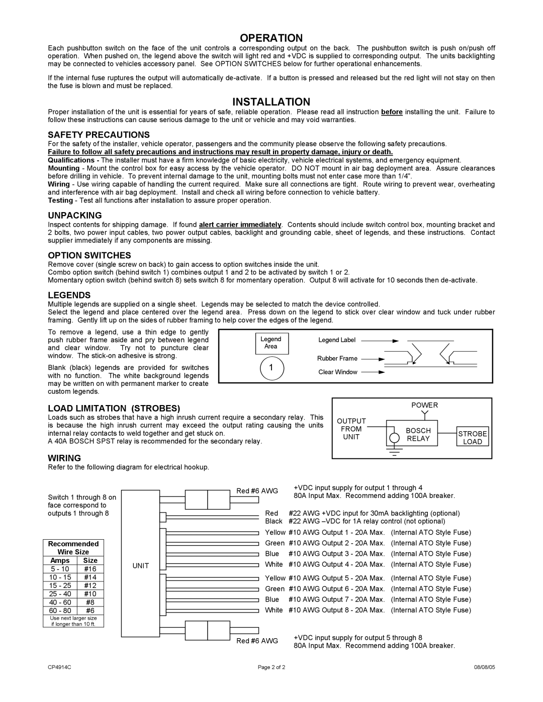
LOAD LIMITATION (STROBES)
Loads such as strobes that have a high inrush current require a secondary relay. This is because the high inrush current may exceed the output rating causing the units internal relay contacts to weld together and get stuck on.
A 40A BOSCH SPST relay is recommended for the secondary relay.
WIRING
Refer to the following diagram for electrical hookup.
| POWER |
| |
OUTPUT |
|
| |
FROM | BOSCH | STROBE | |
UNIT | RELAY | ||
LOAD | |||
|
|
Switch 1 through 8 on face correspond to outputs 1 through 8
Recommended
Wire Size
Amps Size
5 - 10 #16
10 - 15 #14
15 - 25 #12
25 - 40 #10
40 - 60 #8
60 - 80 #6
Use next larger size if longer than 10 ft.
UNIT
|
|
|
| Red #6 AWG | +VDC input supply for output 1 through 4 | |||
|
|
|
| 80A Input Max. Recommend adding 100A breaker. | ||||
|
|
|
|
|
| |||
|
|
|
|
| Red | #22 AWG +VDC input for 30mA backlighting (optional) | ||
|
|
|
|
| ||||
|
|
|
|
| ||||
|
|
|
|
| Black | #22 AWG | ||
|
|
|
|
| ||||
|
|
|
|
| Yellow #10 AWG Output 1 - 20A Max. | (Internal ATO Style Fuse) | ||
|
|
|
|
| Green | #10 AWG Output 2 - 20A Max. | (Internal ATO Style Fuse) | |
|
|
|
|
| Blue | #10 AWG Output 3 - 20A Max. | (Internal ATO Style Fuse) | |
|
|
|
|
| White | #10 AWG Output 4 - 20A Max. | (Internal ATO Style Fuse) | |
|
|
|
|
| Yellow #10 AWG Output 5 | - 20A Max. | (Internal ATO Style Fuse) | |
|
|
|
|
| ||||
|
|
|
|
| Green | #10 AWG Output 6 | - 20A Max. | (Internal ATO Style Fuse) |
|
|
|
|
| Blue | #10 AWG Output 7 | - 20A Max. | (Internal ATO Style Fuse) |
|
|
|
|
| White | #10 AWG Output 8 | - 20A Max. | (Internal ATO Style Fuse) |
|
|
|
|
|
|
|
|
|
|
|
|
|
| +VDC input supply for output 5 through 8 |
|
|
|
|
| |
|
|
| Red #6 AWG | ||
|
|
| 80A Input Max. Recommend adding 100A breaker. | ||
|
|
|
|
| |
CP4914C | Page 2 of 2 | 08/08/05 |