Page 4 |
Wiring - Use wiring capable of handling the current required. Make sure all connections are tight. Route wiring to prevent wear, overheating and interference with air bag deployment. Install and check all wiring before connection to vehicle battery.
Testing - Test all siren functions after installation to assure proper operation. Test vehicle opera- tion to assure no damage to vehicle.
Keep These Instructions - Keep these instructions in the vehicle or other safe place for future reference. Advise the vehicle operator of the location.
UNPACKING
Inspect contents for shipping damage. If found alert carrier immediately. Contents should in- clude unit with attached microphone, mounting bracket, microphone bracket with 2 screws, 2 mounting bolts, connector and these instructions. Contact supplier immediately if any compo- nents are missing.
MOUNTING
The mounting bracket supplied can be installed above or below the unit. Choose a mounting location convenient to the operator and away from any air bag deployment areas. Inspect behind mounting area for clearance. Assure adequate ventilation to prevent overheating. Consider wire routing and access to connections, as well as microphone bracket placement. Install mounting bracket to vehicle using 1/4" hardware (not supplied).
If mounting in a rack or console, make sure that mounting bolts do not enter case more than 1/4".
|
|
|
|
|
|
|
|
|
|
|
|
|
|
|
Carefully cutting programming resistor jumpers |
|
|
|
|
|
|
|
|
|
|
|
|
|
|
|
|
|
|
|
|
|
|
|
|
|
|
|
| |
or traces on the printed circuit board inside the |
|
|
|
|
|
|
|
|
|
|
|
|
|
|
case can select various options. |
|
|
|
|
|
|
|
|
|
|
|
|
|
|
Cover Removal - The cover is held in place by |
| FUSE |
|
|
|
|
|
|
|
|
|
|
|
|
|
|
|
|
|
|
|
|
|
|
|
| |||
a |
|
|
| AUXP |
| CUTP | PHSR | AUXI |
|
| ||||
the unit with the front case flange on the edge |
|
|
|
|
|
| ||||||||
|
|
|
|
|
|
|
|
|
|
|
|
|
| |
of a hard surface and press hard on the back of |
|
|
|
|
|
|
|
|
|
|
|
|
|
|
the unit. The chassis will slide out the front of |
|
|
|
|
|
|
|
|
|
|
|
|
|
|
|
|
|
|
|
|
|
|
|
|
|
|
|
| |
the cover. |
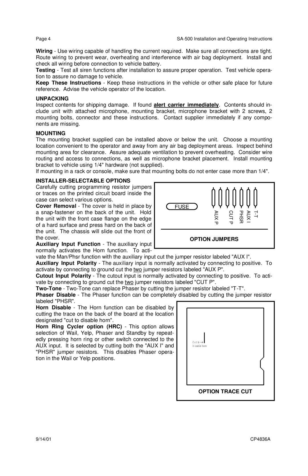
| OPTION JUMPERS |
|
|
|
|
|
|
| |||||
Auxiliary Input Function - The auxiliary input |
|
|
|
|
|
|
|
|
|
|
|
|
|
|
normally activates the Horn function. To acti- |
|
|
|
|
|
|
|
|
|
|
|
|
|
|
vate the Man/Phsr function with the auxiliary input cut the jumper resistor labeled "AUX I". Auxiliary Input Polarity - The auxiliary input is normally activated by connecting to positive. To activate by connecting to ground cut the two jumper resistors labeled "AUX P".
Cutout Input Polarity - The cutout input is normally activated by connecting to positive. To acti- vate by connecting to ground cut the two jumper resistors labeled "CUT P".
Phaser Disable - The Phaser function can be completely disabled by cutting the jumper resistor | |||||
labeled "PHSR". |
|
|
|
|
|
|
|
|
|
| |
Horn Disable - The Horn function can be disabled by |
|
|
|
|
|
cutting the trace on the back of the board at the location |
|
|
|
|
|
designated "cut to disable horn". |
|
|
|
|
|
Horn Ring Cycler option (HRC) - This option allows |
|
|
|
|
|
selection of Wail, Yelp, Phaser and Standby by repeat- |
|
|
|
|
|
|
|
|
|
| |
edly pressing horn ring or other switch connected to the |
| C u t to → |
|
|
|
AUX input. It is selected by cutting both the "AUX I" and |
| D isable horn |
| ||
"PHSR" jumper resistors. This disables Phaser opera- |
|
|
|
|
|
tion in the Wail or Yelp positions. |
|
|
|
|
|
|
|
|
|
| |
|
|
|
| ||
|
|
|
|
| |
|
| OPTION TRACE CUT | |||
|
|
|
|
|
|
9/14/01 | CP4836A |