CPU (LSI1: MSM6755B-13)
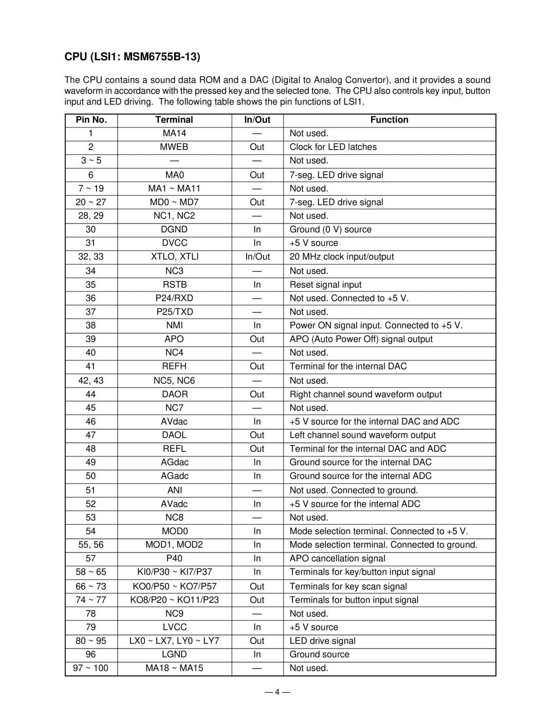
The CPU contains a sound data ROM and a DAC (Digital to Analog Convertor), and it provides a sound waveform in accordance with the pressed key and the selected tone. The CPU also controls key input, button input and LED driving. The following table shows the pin functions of LSI1.
Pin No. | Terminal | In/Out | Function |
1 | MA14 | — | Not used. |
2 | MWEB | Out | Clock for LED latches |
3 ~ 5 | — | — | Not used. |
6 | MA0 | Out | |
7 ~ 19 | MA1 ~ MA11 | — | Not used. |
20 ~ 27 | MD0 ~ MD7 | Out | |
28, 29 | NC1, NC2 | — | Not used. |
30 | DGND | In | Ground (0 V) source |
31 | DVCC | In | +5 V source |
32, 33 | XTLO, XTLI | In/Out | 20 MHz clock input/output |
34 | NC3 | — | Not used. |
35 | RSTB | In | Reset signal input |
36 | P24/RXD | — | Not used. Connected to +5 V. |
37 | P25/TXD | — | Not used. |
38 | NMI | In | Power ON signal input. Connected to +5 V. |
39 | APO | Out | APO (Auto Power Off) signal output |
40 | NC4 | — | Not used. |
41 | REFH | Out | Terminal for the internal DAC |
42, 43 | NC5, NC6 | — | Not used. |
44 | DAOR | Out | Right channel sound waveform output |
45 | NC7 | — | Not used. |
46 | AVdac | In | +5 V source for the internal DAC and ADC |
47 | DAOL | Out | Left channel sound waveform output |
48 | REFL | Out | Terminal for the internal DAC and ADC |
49 | AGdac | In | Ground source for the internal DAC |
50 | AGadc | In | Ground source for the internal ADC |
51 | ANI | — | Not used. Connected to ground. |
52 | AVadc | In | +5 V source for the internal ADC |
53 | NC8 | — | Not used. |
54 | MOD0 | In | Mode selection terminal. Connected to +5 V. |
55, 56 | MOD1, MOD2 | In | Mode selection terminal. Connected to ground. |
57 | P40 | In | APO cancellation signal |
58 ~ 65 | KI0/P30 ~ KI7/P37 | In | Terminals for key/button input signal |
66 ~ 73 | KO0/P50 ~ KO7/P57 | Out | Terminals for key scan signal |
74 ~ 77 | KO8/P20 ~ KO11/P23 | Out | Terminals for button input signal |
78 | NC9 | — | Not used. |
79 | LVCC | In | +5 V source |
80 ~ 95 | LX0 ~ LX7, LY0 ~ LY7 | Out | LED drive signal |
96 | LGND | In | Ground source |
97 ~ 100 | MA18 ~ MA15 | — | Not used. |
— 4 —