CPU (LSI101: MSM6387-22)
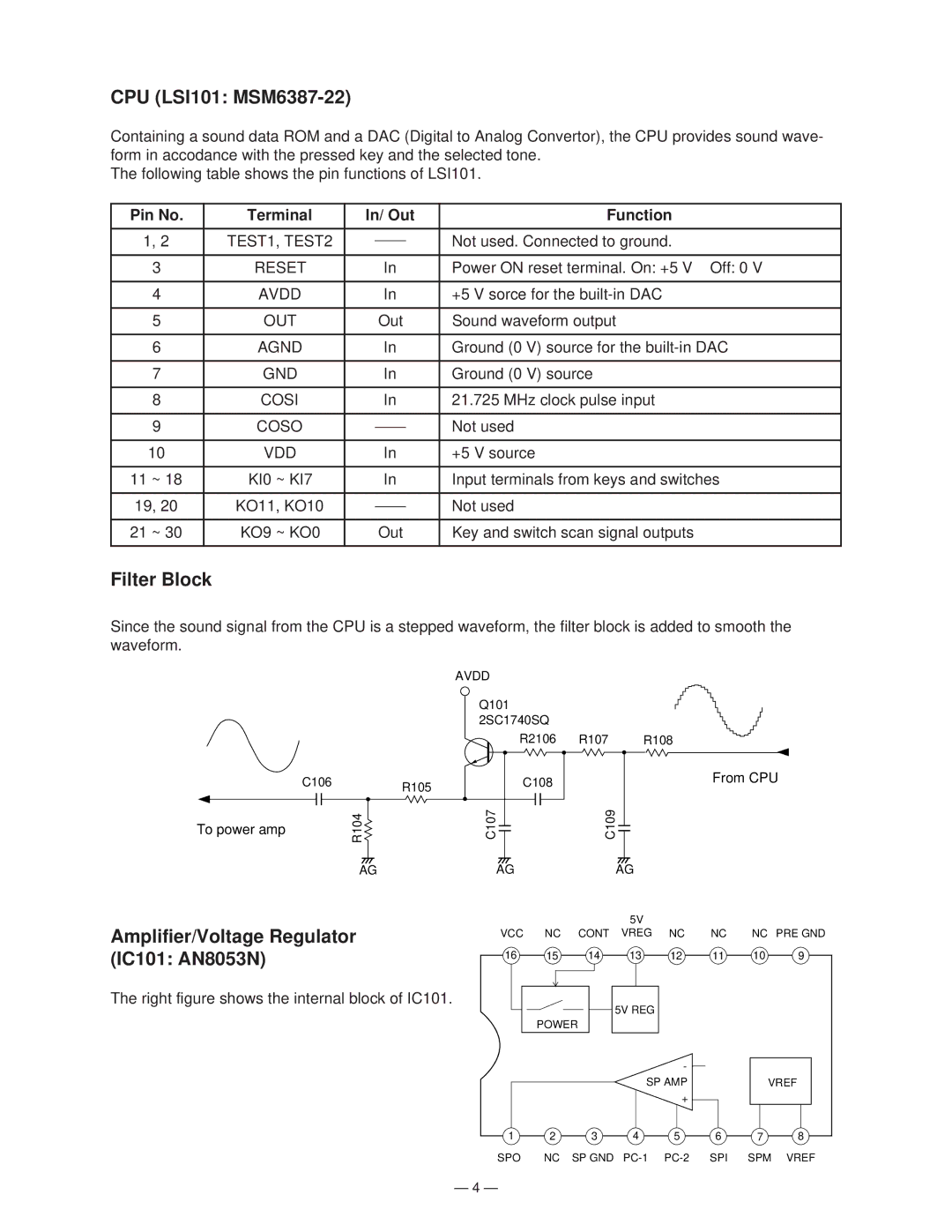
Containing a sound data ROM and a DAC (Digital to Analog Convertor), the CPU provides sound wave- form in accodance with the pressed key and the selected tone.
The following table shows the pin functions of LSI101.
Pin No. | Terminal | In/ Out | Function | ||
|
|
|
|
|
|
1, 2 | TEST1, TEST2 |
|
|
| Not used. Connected to ground. |
|
|
| |||
|
|
|
|
| |
3 | RESET |
| In | Power ON reset terminal. On: +5 V Off: 0 V | |
|
|
|
|
| |
4 | AVDD |
| In | +5 V sorce for the | |
|
|
|
|
| |
5 | OUT |
| Out | Sound waveform output | |
|
|
|
|
| |
6 | AGND |
| In | Ground (0 V) source for the | |
|
|
|
|
| |
7 | GND |
| In | Ground (0 V) source | |
|
|
|
|
| |
8 | COSI |
| In | 21.725 MHz clock pulse input | |
|
|
|
|
|
|
9 | COSO |
|
|
| Not used |
|
|
| |||
|
|
|
|
| |
10 | VDD |
| In | +5 V source | |
|
|
|
|
| |
11 ~ 18 | KI0 ~ KI7 |
| In | Input terminals from keys and switches | |
|
|
|
|
|
|
19, 20 | KO11, KO10 |
|
|
| Not used |
|
|
| |||
|
|
|
|
| |
21 ~ 30 | KO9 ~ KO0 |
| Out | Key and switch scan signal outputs | |
|
|
|
|
|
|
Filter Block
Since the sound signal from the CPU is a stepped waveform, the filter block is added to smooth the waveform.
To power amp
C106R105
R104![]()
AG
AVDD
Q101
2SC1740SQ
R2106 R107 R108
| C108 |
C107 | C109 |
AG | AG |
From CPU
Amplifier/Voltage Regulator |
|
|
| 5V |
|
|
|
|
VCC | NC | CONT | VREG | NC | NC | NC PRE GND | ||
|
|
|
|
|
|
|
| |
(IC101: AN8053N) | 16 | 15 | 14 | 13 | 12 | 11 | 10 | 9 |
|
|
|
|
|
|
|
| |
The right figure shows the internal block of IC101. |
|
|
| 5V REG |
|
|
|
|
|
|
|
|
|
|
|
| |
|
| POWER |
|
|
|
|
| |
|
|
|
|
| - |
|
|
|
|
|
|
| SP AMP |
| VREF | ||
|
|
|
|
| + |
|
|
|
| 1 | 2 | 3 | 4 | 5 | 6 | 7 | 8 |
| SPO | NC | SP GND | SPI | SPM | VREF | ||
— 4 —
