IMPORTANT NOTICE
ABOUT INSTALLATION | Copyright© 2001 CAT EYE Co.,Ltd. | E | |
066600110 | |||
| 1 Printed in Japan | ||
In order to make this model suitable for MTB, some of the parts have been changed.
When mounting to bicycle, follow the explanation written in this sheet, not the instruction manual.
Parts | 4 | 8 | 1 | 5 | 6 | |
1 Bracket | ||||||
| ||||||
2 Wire |
|
|
|
|
| |
3 Sensor | 3 |
|
|
|
| |
4 Magnet |
|
|
|
| ||
| 2 |
|
|
| ||
5 Bracket Rubber Pad (2 pcs.) |
|
|
| 7 | ||
6 Nylon Tie (5 pcs.) |
|
|
|
| ||
|
|
|
|
|
7 Spiral Tube
8Lithium Battery CR2032
1.Installation (Instead of following the explanation in
S S O R I E S
#169-9730N Heavy Duty Wire and Bracket Sensor Kit
Kit de Fil Renforce et Supports d´Unité Principale et de Détecteur
Nachrüstset mit Halterung, Sensor und verstärktem Sensorkabel
Filo Ultra Resistente e Attacco Completo
Kit Soporte del Sensor y Alambre de Servicio Pesado
Extra sterke kabel en bracket sensor set
ヘビーデューティブラケットセンサーキット
#169-6560N[#169-6565N] Bracket Sensor Kit [Long]
| Kit de montage de l'unité principale et du détecteur [Longs] |
| Halterung und Sensorkabel [Lang] |
| Kit supporto unità principale e sensore [Lunghi] |
| Kit Soporte del Sensor [Largo] |
| bracket sensor kit |
| ブラケットセンサーキット[ロング] |
| Center Mount Bracket Kit [Long] |
| Kit de montage central de l'unité principale [Longs] |
| Halterung für Montage an der Lenkermitte [Lang] |
| Kit di montaggio al centro del manubrio [Lunghi] |
| Kit Soporte para Montaje Central [Largo] |
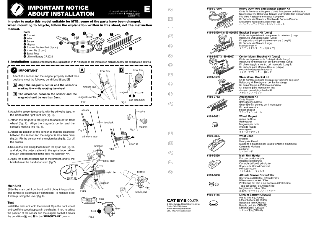
IMPORTANT | A | front fork |
Attach the sensor and the magnet properly so that their |
| |
positions meet the following conditions A and B . |
|
|
A Align the magnet’s center and the sensor’s | marking line |
|
marking line while rotating the wheel. |
| |
|
| |
B The clearance between the sensor and the | magnet’s center |
|
magnet should be less than 5mm. |
| |
| Fig.1 |
|
1. Attach the sensor temporarily, with the adhesive tape, to | sensor |
|
|
| |
the inside of the right front fork (fig. 3). |
|
|
B | front fork |
| sensor |
magnet
less than 5mm
Fig.2
spoke
A C C E
| centrum bevestigings bracket kit |
| センターマウントキット[ロング] |
| Stem Mount Bracket Kit |
| Kit de montage de l'unité principale sur la broche du guidon |
| Halterung für Montage an der Lenkerstange |
| Kit di montaggio sull'attacco manubrio |
| Kit Soporte para Montaje en Tija |
| stuurpen bevestigings bracket kit |
| ステムマウントキット |
| Attachment Kit |
| Kit de Fixation |
| Befestigungsmaterial |
| Guarnizioni in gomma per il montaggio |
| Kit de Accesorios |
| bevestigings kit |
| アタッチメントキット |
| Wheel Magnet |
2.Attach the magnet to the right side spoke of the front wheel (fig. 4). Align the magnet’s center and the sensor’s marking line (fig. 1).
3.Adjust the position of the sensor so that the clearance between the sensor and the magnet is less than 5mm (fig. 2). Fix the sensor with the nylon ties (fig.5). Cut off the excess.
4.Secure the wire along the fork with the nylon ties (fig. 6), and along the outer cable with the spiral tube. Allow enough wire clearance in the area marked with ![]() .
.
front fork
Fig.3
adhesive tape
bracket ![]() Fig.5
Fig.5
magnet
Fig.4
nylon tie
A R E
| Aimant de Roue |
| Radmagnet |
| Magnete per ruota |
| Imán de Rueda |
| wielmagneet |
| ホイールマグネット |
| Wrist Band |
| Bracelet |
| Handgelenkband |
| Supporto a bracciale per la sola funzione di altimetro |
| Correa de Muñeca |
| polsband |
| リストバンド |
| Main Unit Holder |
5. Apply the bracket rubber pad to the bracket, and fix the bracket near the handlebar stem.(fig.7)
nylon tie
Main Unit
spiral tube
nylon tie | bracket |
sensor
S P
| Etui pour unité principale |
| Hauptgeräthalterung |
| Custodia dell'unità principale |
| Soporte de Unidad Principal |
| computer houder |
| メインユニットフォルダー |
| Altitude Sensor Cover/Filter |
| Couvercle du Détecteur d'Altitude/Filtre |
| Höhensensordeckel / Filter |
| Protezione del filtro e del sensore dell'altitudine |
| Tapa del Sensor de Altitud/Filtro |
| hoogtesensor deksel / filter |
Slide the main unit from front until it clicks into position. | Fig.6 | rubber pad | |
The contact is automatically connected. To remove, slide | |||
| |||
it while pushing the lever (fig. 8). |
| Fig.7 | |
|
| slide |
Test
Install the main unit onto the bracket. Spin the front wheel
and see if the speed appears in the display. If not, | lever | |
front | ||
the position of the sensor and the magnet so that it meets | ||
| ||
the conditions A and B in the “IMPORTANT” column. | Fig.8 |
![]()
![]()
![]()
![]()
![]() CO.,LTD.
CO.,LTD.
URL: http://www.cateye.com
| 高度センサーキャップ/フィルター |
|
|
Lithium Battery (CR2032) | |
| Pile au lithium (CR2032) |
| Lithiumbatterie (CR2023) |
| Batteria al litio (CR2032) |
Batería de Litio (CR2032) Lithium batterij (CR2032) リチウム電池(CR2032)