CATEYE STRADA DOUBLE WIRELESS | |
CYCLOCOMPUTER | |
ENG | 0678 |
U�S� Pat� Nos� 5236759/6957926 Pat�/Design Pat� Pending | |
Copyright© 2008 CATEYE Co�, Ltd� | |
| |
![]() WARNING / CAUTION
WARNING / CAUTION
• | Do not concentrate on the computer while riding� Ride safely! |
• | Install the magnet, sensor, and bracket securely� Check these periodically� |
• | If a child swallows a battery, consult a doctor immediately� |
• | Do not leave the computer in direct sunlight for a long period of time� |
• Do not disassemble the computer� | |
• Do not drop the computer to avoid malfunction or damage� | |
• When using the computer installed on the bracket, change the MODE by pressing on the three dots below the | |
| screen� Pressing hard on other areas can result in malfunction or damage to the computer� |
• | Tighten the dial on the FlexTight bracket by hand only� |
• | When cleaning the computer, bracket and sensor, do not use thinners, benzene, or alcohol� |
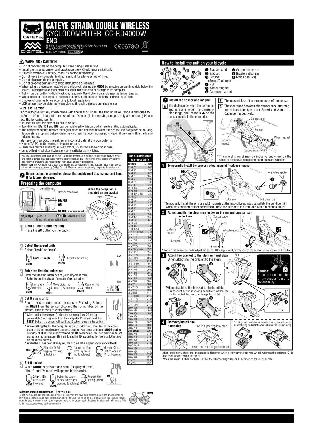
How to install the unit on your bicycle
2 5 | 7 | 1 Bracket band | 7 Sensor rubber pad | |
1 | 2 Bracket | 8 Bracket rubber pad | ||
| ||||
6 |
| 3 Sensor | 9 Nylon ties (x3) | |
|
| (Speed/Cadence) |
|
|
| 8 |
| 4 Nut |
4 | 3 |
|
| |
|
| 5 Wheel magnet | ||
|
|
| ||
|
|
|
| |
|
|
| 9 | 6 Cadence magnet |
|
|
|
|
• | Dispose of used batteries according to local regulations� |
• | LCD screen may be distorted when viewed through polarized sunglass lenses� |
Wireless Sensor
In order to prevent any interference with the sensor signal, the transmission range is designed to be 20 to 100 cm, in addition to use of the ID code� (This receiving range is only a reference�) Please note the following points�
•To use this unit, the sensor ID has to be set�
•Two different IDs, ID1 and ID2, can be registered to this unit, which are identified automatically�
•The computer cannot receive the signal when the distance between the sensor and computer is too long� Temperature drop and battery drain may worsen the receiving sensitivity even if they are within the trans- mission range�
A
Install the sensor and magnet
The distance between the computer and sensor is within the transmis- sion range, and the mark ![]() on the sensor points to the computer�
on the sensor points to the computer�
BThe magnet faces the sensor zone of the sensor�
CThe clearance between the sensor face and mag- net is less than 5 mm for Speed and 3 mm for Cadence, respectively�
3 mm | Sensor zone |
| ||
|
|
|
| |
|
|
| ||
|
| Sensor |
| |
|
|
|
| Wheel magnet |
Interference may occur, resulting in incorrect data, if the computer is:
•Near a TV, PC, radio, motor, or in a car or train�
•Close to a railroad crossing, railway tracks, TV stations and/or radar base�
•Using with other wireless devices, or some particular battery lights�
This device complies with Part 15 of the FCC Rules� Operation is subject to the following two condi- tions:(1)This device may not cause harmful interference, and (2) this device must accept any interfer- ence received, including interference that may cause undesired operation�
Modifications The FCC requires the user to be notified that any changes or modifications made to this device that are not expressly approved by CatEye Co�, Ltd� May void the user ’s authority to operate the equipment�
Before using the computer, please thoroughly read this manual and keep it for future reference.
Preparing the computer
When the computer is
Battery case cover mounted on the bracket
Push!
| MENU |
| AC |
| MODE |
km/h mph : Speed unit | : Wheel size icon |
: Sensor signal reception icon
1
AC![]()
2 Select the speed units Select “km/h” or “mph”�
Tire circumference
reference table
Tire size | L (mm) |
12 x1.75 | 935 |
12 x1.95 | 940 |
14 x1.50 | 1020 |
14 x1.75 | 1055 |
16 x1.50 | 1185 |
16 x1.75 | 1195 |
16 x2.00 | 1245 |
16 | 1290 |
16 | 1300 |
17 | 1340 |
18 x1.50 | 1340 |
18 x1.75 | 1350 |
20 x1.25 | 1450 |
20 x1.35 | 1460 |
20 x1.50 | 1490 |
20 x1.75 | 1515 |
20 x1.95 | 1565 |
20 | 1545 |
20 | 1615 |
22 | 1770 |
22 | 1785 |
24 x1 (520) | 1753 |
24 x 3/4 Tubular | 1785 |
24 x | 1795 |
24 x | 1905 |
24 x 1.75 | 1890 |
24 x 2.00 | 1925 |
24 x 2.125 | 1965 |
26 x 7/8 Tubular | 1920 |
26 x 1 (571) | 1952 |
Cadence | 5 mm |
magnet
Sensor zone ![]()
![]()
*The wheel magnet may be installed anywhere on the spoke if the above installation conditions are satisfied�
1Temporarily install the sensor / wheel magnet / cadence magnet
3 | Rear wheel spoke |
| 5 |
7 |
|
6 |
|
Left crank | Left Chain Stay |
*Temporarily install the sensor and 2 magnets at the respective points that satisfy the condition B � When the condition cannot be satisfied, move the sensor in the
2Adjust and fix the clearance between the magnet and sensor
3 mm | Sensor screw |
|
| Speed |
|
Cadence | Wheel magnet |
|
magnet |
| |
|
| |
Cadence |
|
|
| 5 mm | 9 |
|
|
* Loosen the sensor screw to adjust the speed� After adjustment, firmly tighten the sensor screw and nylon tie to fix�
km/h ↔ mph ![]()
![]() Register the setting
Register the setting
MODE![]() MENU
MENU
Enter the tire circumference |
|
| |
3 Enter the tire circumference of your bicycle in mm� | |||
* Refer to the tire circumference reference table� |
| ||
I n c r e a s e | Move digits (by |
| Register the |
the value | pressing & holding) | MENU | setting |
MODE | MODE |
| |
|
| ||
|
|
| |
4 Set the sensor ID
Place the computer near the sensor� Pressing & hold- ing RESET on the sensor displays the ID number on the screen, then moves to clock setting�
26 x | 1970 |
26 x | 2068 |
26 x | 2100 |
26 x 1.0 (559) | 1913 |
26 x 1.25 | 1950 |
26 x 1.40 | 2005 |
26 x 1.50 | 2010 |
26 x 1.75 | 2023 |
26 x 1.95 | 2050 |
26 x 2.00 | 2055 |
26 x 2.1 | 2068 |
26 x 2.125 | 2070 |
26 x 2.35 | 2083 |
26 x 3.00 | 2170 |
27 x 1 (630) | 2145 |
27 x | 2155 |
27 x | 2161 |
27 x | 2169 |
650 x 20C | 1938 |
650 x 23C | 1944 |
3Attach the bracket to the stem or handlebar When attaching the bracket to the stem
8
2![]()
![]() 1
1
When attaching the bracket to the handlebar
*On account of the receiving sensitivity, attach the bracket so that the computer is kept horizontal�
8
1 ![]()
![]() 2
2
Stem
 Cut
Cut
Caution: ![]() Round off the cut edge of the bracket band to prevent injury�
Round off the cut edge of the bracket band to prevent injury�
Handlebar
![]()
![]() 4
4
* When setting the sensor ID, place the sensor at least 20 cm (ap- proximately 8 inches) away from the computer� Press and hold the RESET button, the sensor will send the ID when releasing the button�
*While setting the ID, the computer is on Standby for 5 minutes� If the com- puter does not receive any sensor signal, or you press and hold MODE during Standby, “ERROR” is displayed and the ID is canceled� You can continue to set up, but cannot measure� Be sure to set the ID according to “Sensor ID Setting” on the menu screen�
*When the ID has been already set, the original ID is applied if you cancel the ID�
RESET |
| Start the ID Set- | Cancel the ID or | Move to Clock | ||
| ting (by pressing | reset (by press- | Setting when no | |||
|
| |||||
|
| & holding) |
| ing & holding) | MENU ID has been set. | |
|
|
|
| MODE |
|
|
Set the clock |
|
|
|
|
| |
5 When MODE is pressed and held, “Displayed time”, |
| |||||
“Hour”, and “Minute” will appear, in this order� |
| |||||
| 24h↔12h, | Switch the screen | Register the | |||
| or increase | or move digits (by | setting (finish) | |||
MODE the value | MODE | pressing & holding) | MENU |
| ||
650 x 35A | 2090 |
650 x 38A | 2125 |
650 x 38B | 2105 |
700 x 18C | 2070 |
700 x 19C | 2080 |
700 x 20C | 2086 |
700 x 23C | 2096 |
700 x 25C | 2105 |
700 x 28C | 2136 |
700 x 30C | 2146 |
700 x 32C | 2155 |
700C Tubular | 2130 |
700 x 35C | 2168 |
700 x 38C | 2180 |
700 x 40C | 2200 |
700 x 44C | 2224 |
29 x 2.1 | 2288 |
29 x 2.3 | 2326 |
4 Remove/install the | * For wing type handlebar or oversized stem, bracket can be | |
computer | While supporting it by hand, | mounted using the bracket holder and nylon ties� (Option parts) |
Click |
|
|
|
| 2 |
| push it out as if lifting the front up |
|
*After installment, check that the speed is displayed when gently turning the rear wheel, whereas the cadence (C) is displayed when turning the crank�
*When the sensor ID has not been set, set the ID according “Sensor ID setting” on the menu screen�
Measure wheel circumference (L) of your bike | L mm | |
To get the most accurate calibration do a wheel roll out. With the valve stem perpendicular to the ground, mark the | ||
| ||
pavement at the valve stem. With the riders weight on the bike, roll the wheel one tire revolution in a straight line and |
| |
mark the ground when the valve stem is perpendicular to the ground again. Measure the distance in millimeters. This |
| |
is the most accurate wheel calibration number. |
|