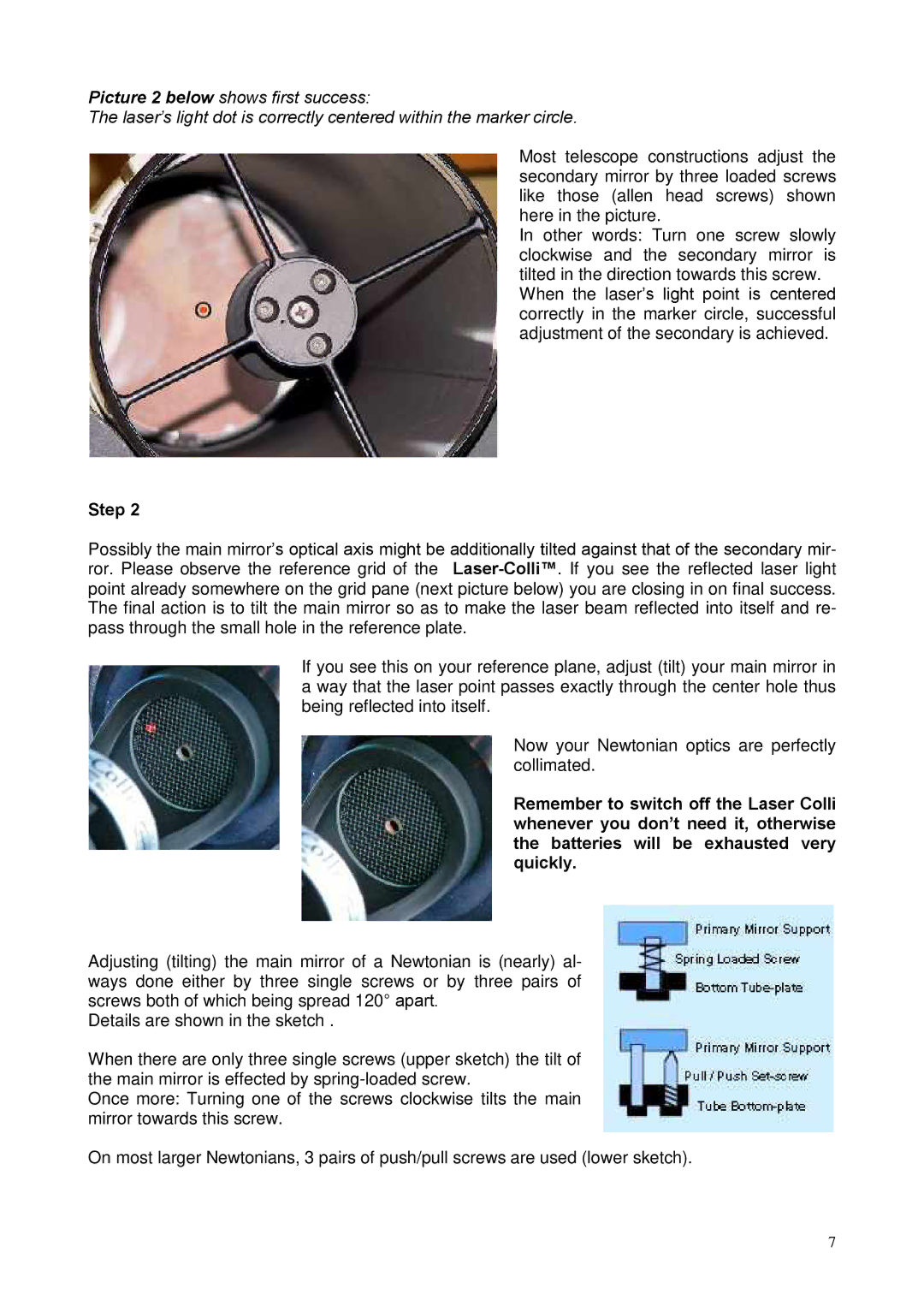
Picture 2 below shows first success:
The laser’s light dot is correctly centered within the marker circle.
Most telescope constructions adjust the secondary mirror by three loaded screws like those (allen head screws) shown here in the picture.
In other words: Turn one screw slowly clockwise and the secondary mirror is
tilted in the direction’s lighttowardspointthisis centeredscrew. When the laser
correctly in the marker circle, successful adjustment of the secondary is achieved.
Step 2
Possibly the main mirror’s optical axis might be additionally tilted against that of the secondary mir- | |
ror. Please observe the reference grid of the | |
point already somewhere on the grid pane (next picture below) you are closing in on final success. The final action is to tilt the main mirror so as to make the laser beam reflected into itself and re- pass through the small hole in the reference plate.
If you see this on your reference plane, adjust (tilt) your main mirror in a way that the laser point passes exactly through the center hole thus being reflected into itself.
Now your Newtonian optics are perfectly collimated.
Remember to switch off the Laser Colli whenever you don’t need it, otherwise the batteries will be exhausted very quickly.
Adjusting (tilting) the main mirror of a Newtonian is (nearly) al-
ways done either by three single screws° apartor. by three pairs of screws both of which being spread 120
Details are shown in the sketch .
When there are only three single screws (upper sketch) the tilt of the main mirror is effected by
Once more: Turning one of the screws clockwise tilts the main mirror towards this screw.
On most larger Newtonians, 3 pairs of push/pull screws are used (lower sketch).
7