Maintenance of Motors

The motors used on the fan and the drum assembly are prelubricated for extended bearing life and require no further lubrication. However, periodic cleaning/vac- uuming of the fan/heater and around the air intake, located under the top shelf (Fig. 4), is recommended.

Make sure the power is turned OFF before proceeding.

Cleaning

Cleaning of the touchpad label at the bottom front of the unit is to be done only using a soft cloth, slightly dampened in water (if needed, a small amount of dish soap can be added to the water) and dried using a clean, dry soft cloth. Cleaning of the screen diffuser is to be done using only water and a lint free cloth. DO NOT use any abrasive household cleaners as these products will damage the touchpad controls and the diffusing screen.

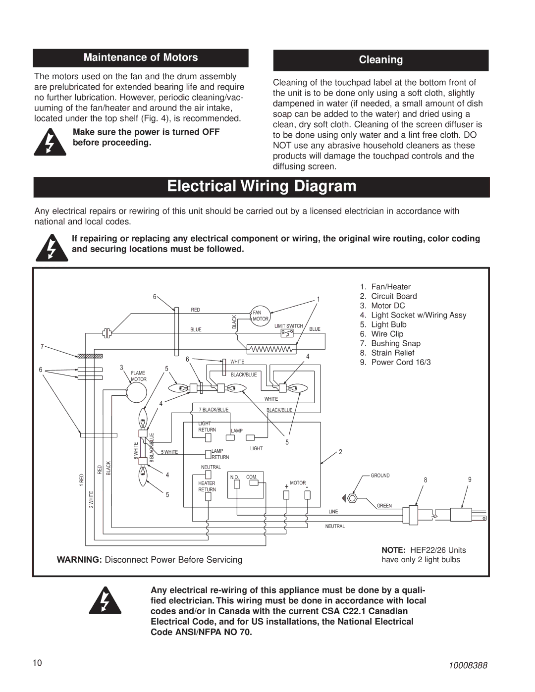
Electrical Wiring Diagram

Any electrical repairs or rewiring of this unit should be carried out by a licensed electrician in accordance with national and local codes.

If repairing or replacing any electrical component or wiring, the original wire routing, color coding and securing locations must be followed.


1.

Fan/Heater


6


1

2.

Circuit Board


3.

Motor DC


RED


FAN


4. Light Socket w/Wiring Assy


BLACK


MOTOR


5.

Light Bulb


BLUE


LIMIT SWITCH


BLUE


6.

Wire Clip


7


7.

Bushing Snap


8.

Strain Relief


6


4


WHITE


9.

Power Cord 16/3


6


3


5


FLAME


BLACK/BLUE


MOTOR


4


WHITE


7 BLACK/BLUE


BLACK/BLUE


LIGHT


BLACK/BLUE


RETURN

LAMP


6 WHITE


LIGHT

5


5 WHITE

LAMP


2


RETURN


RED

BLACK

8


NEUTRAL


RED

4


N.O.

COM.


GROUND

9


HEATER


+

MOTOR

-


8

1


2 WHITE


5

RETURN


LINE

GREEN


NEUTRAL


NOTE: HEF22/26 Units


WARNING: Disconnect Power Before Servicing


have only 2 light bulbs


Any electrical re-wiring of this appliance must be done by a quali- fied electrician. This wiring must be done in accordance with local codes and/or in Canada with the current CSA C22.1 Canadian Electrical Code, and for US installations, the National Electrical Code ANSI/NFPA NO 70.

10

10008388

Page 10
Image 10
CFM Corporation HEF33, HEF26 installation instructions Electrical Wiring Diagram, Maintenance of Motors, Cleaning

HEF26, HEF33 specifications

CFM Corporation is renowned for its commitment to excellence in the aerospace industry, particularly through its innovative jet propulsion systems. Among its notable offerings are the CFM HEF33 and HEF26 models, each designed to deliver superior performance and reliability in various aviation applications.

The CFM HEF33 is engineered with cutting-edge technologies, offering exceptional thrust capabilities while maintaining efficiency. One of its standout features is the advanced bypass ratio, which allows for a significant reduction in noise pollution and fuel consumption. This model incorporates composite fan blades that enhance aerodynamic efficiency and durability. Additionally, the HEF33 utilizes state-of-the-art materials that withstand high temperatures and mechanical stresses, ensuring long service life and reduced maintenance needs. The engine's modular design further simplifies repairs and facilitates quicker turnaround times, making it a preferred choice for operators seeking reliability and performance.

In contrast, the CFM HEF26 targets a slightly different market segment but shares a focus on performance and efficiency. This model features a streamlined design that reduces drag and optimizes airflow, contributing to its impressive fuel economy. The HEF26 also benefits from advanced thermal management systems that maintain optimal operating temperatures, extending the engine's lifespan and enhancing overall resilience. Moreover, the incorporation of cutting-edge engine control technologies allows for precise performance monitoring and adjustments in real-time, enabling pilots to maximize efficiency during flight.

Both models reflect CFM Corporation's dedication to sustainability and environmental responsibility. The HEF33 and HEF26 are designed to meet stringent emission standards, minimizing their ecological footprint. Furthermore, these engines are compatible with sustainable aviation fuels, paving the way for greener aviation practices.

In summary, the CFM HEF33 and HEF26 engines exemplify technological prowess and commitment to quality in the aerospace sector. With their impressive features, such as advanced aerodynamics, modular designs, and environmentally friendly technologies, both models provide operators with reliable and efficient solutions for modern aviation challenges. CFM Corporation continues to lead the way in shaping the future of aviation propulsion, ensuring safety, performance, and sustainability are always at the forefront.