|
|
|
|
| 00985 Wireless refrigerator & Freezer Thermometer |
|
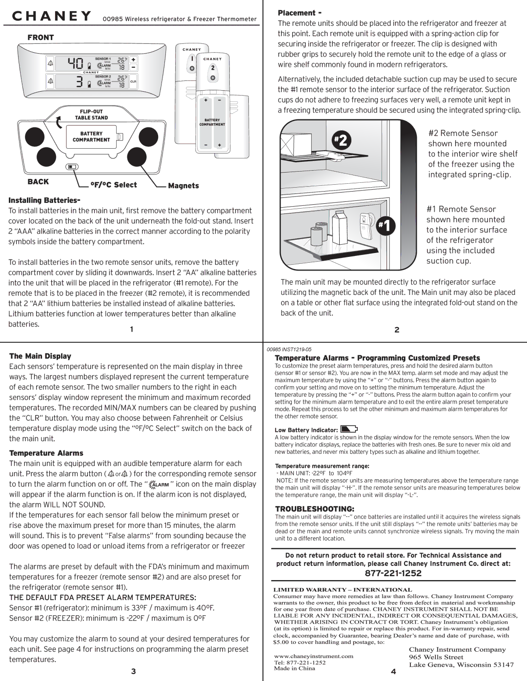
| Placement - |
|
| |||||||||||||||
|
|
|
|
|
|
| The remote units should be placed into the refrigerator and freezer at | ||||||||||||||||||
|
|
|
|
|
|
|
|
|
|
|
|
|
|
|
|
| |||||||||
|
|
|
|
|
|
|
|
|
|
|
|
|
|
| |||||||||||
| FRONT |
|
|
|
|
|
|
|
|
|
|
|
|
| this point. Each remote unit is equipped with a | ||||||||||
|
|
|
|
|
|
|
|
|
|
|
|
|
| securing inside the refrigerator or freezer. The clip is designed with | |||||||||||
|
|
|
|
|
|
|
|
|
|
|
|
|
|
|
|
| |||||||||
| 40 |
| MAX |
| 26 F |
|
|
|
|
|
|
| rubber grips to securely hold the remote unit to the edge of a glass or | ||||||||||||
|
| SENSOR 1 |
|
|
|
|
|
|
|
|
|
|
| wire shelf commonly found in modern refrigerators. | |||||||||||
|
| MIN |
|
|
|
|
| 2 |
|
|
| ||||||||||||||
|
| 18 |
|
|
| ||||||||||||||||||||
| 3 |
| ALARM | 26 |
|
|
|
|
|
|
|
|
|
|
|
|
|
|
|
|
| ||||
|
| SENSOR 2 | F CLR |
|
|
|
|
|
| Alternatively, the included detachable suction cup may be used to secure | |||||||||||||||
|
|
|
|
|
|
|
| ||||||||||||||||||
|
| MAX |
|
|
|
|
|
| |||||||||||||||||
|
| ALARM | 18 |
|
|
|
|
|
|
|
|
|
|
|
|
|
|
|
| ||||||
|
| MIN |
|
|
|
|
|
|
| the #1 remote sensor to the interior surface of the refrigerator. Suction | |||||||||||||||
|
|
|
|
|
|
|
|
|
|
|
|
|
|
|
|
| |||||||||
|
|
|
|
|
|
|
|
|
|
|
|
|
|
|
|
| cups do not adhere to freezing surfaces very well, a remote unit kept in | ||||||||
|
|
|
|
|
|
|
|
|
|
|
|
|
|
| |||||||||||
|
|
|
|
|
|
|
|
|
|
|
|
|
|
| |||||||||||
|
|
|
|
|
|
|
|
|
|
|
|
|
| a freezing temperature should be secured using the integrated | |||||||||||
|
|
| TABLE STAND |
|
|
|
|
|
| BATTERY |
|
|
|
|
|
|
|
|
|
|
| ||||
|
|
|
|
|
|
|
|
|
|
|
|
|
|
|
|
|
|
|
|
|
|
| |||
|
|
|
|
|
|
|
|
|
|
|
| COMPARTMENT |
|
|
|
|
|
|
|
|
|
|
| ||
|
|
| BATTERY |
|
|
|
|
|
|
|
|
|
| #2 |
|
|
|
|
| #2 Remote Sensor | |||||
|
|
| COMPARTMENT |
|
|
|
|
|
|
|
|
|
|
|
|
|
|
| shown here mounted | ||||||
|
|
|
|
|
|
|
|
|
| ||||||||||||||||
|
|
|
|
|
|
|
|
|
|
|
|
|
|
| |||||||||||
|
|
|
|
|
|
|
|
|
|
|
|
|
|
|
|
|
|
|
|
|
|
|
| to the interior wire shelf | |
|
|
|
|
|
|
|
|
|
|
|
|
|
|
|
|
|
|
|
|
|
|
|
| of the freezer using the | |
| BACK |
|
|
|
|
|
|
|
|
|
|
|
|
|
|
|
|
|
|
|
| integrated | |||
| ºF/ºC Select | Magnets |
|
|
|
|
|
|
|
|
|
|
| ||||||||||||
|
|
|
|
|
|
|
|
|
|
|
|
|
|
| |||||||||||
| Installing Batteries- |
|
|
|
|
|
|
|
|
|
|
|
|
|
|
|
|
|
|
|
| #1 Remote Sensor | |||
| To install batteries in the main unit, first remove the battery compartment |
|
|
|
|
|
|
|
|
| |||||||||||||||
| cover located on the back of the unit underneath the |
| #1 | shown here mounted | |||||||||||||||||||||
| 2 “AAA” alkaline batteries in the correct manner according to the polarity |
| to the interior surface | ||||||||||||||||||||||
| symbols inside the battery compartment. |
|
|
|
|
|
|
|
|
|
|
|
|
| of the refrigerator | ||||||||||
|
|
|
|
|
|
|
|
|
|
|
|
|
|
|
|
|
|
|
|
|
|
|
| using the included | |
| To install batteries in the two remote sensor units, remove the battery |
|
|
|
|
|
|
|
|
| suction cup. | ||||||||||||||
| compartment cover by sliding it downwards. Insert 2 “AA” alkaline batteries |
|
| The main unit may be mounted directly to the refrigerator surface | |||||||||||||||||||||
| into the unit that will be placed in the refrigerator (#1 remote). For the |
|
| ||||||||||||||||||||||
| remote that is to be placed in the freezer (#2 remote), it is recommended |
|
| utilizing the magnetic back of the unit. The Main unit may also be placed | |||||||||||||||||||||
| that 2 “AA” lithium batteries be installed instead of alkaline batteries. |
|
| on a table or other flat surface using the integrated | |||||||||||||||||||||
| Lithium batteries function at lower temperatures better than alkaline |
|
| back of the unit. |
|
| |||||||||||||||||||
| batteries. |
|
| 1 |
|
|
|
|
|
| 2 |
|
| ||||||||||||
|
|
|
|
|
|
|
|
|
|
|
|
|
| ||||||||||||
|
|
|
|
|
|
|
|
|
|
|
|
|
|
|
|
|
|
|
|
|
|
|
|
|
|
| The Main Display |
|
|
|
|
|
|
|
|
|
|
|
| 00985 |
|
| |||||||||
|
|
|
|
|
|
|
|
|
|
|
|
|
| Temperature Alarms - Programming Customized Presets | |||||||||||
| Each sensors’ temperature is represented on the main display in three |
|
| To customize the preset alarm temperatures, press and hold the desired alarm button | |||||||||||||||||||||
| ways. The largest numbers displayed represent the current temperature |
|
| (sensor #1 or sensor #2). You are now in the MAX temp. alarm set mode and may adjust the | |||||||||||||||||||||
|
|
| maximum temperature by using the “+” or | ||||||||||||||||||||||
| of each remote sensor. The two smaller numbers to the right in each |
|
| ||||||||||||||||||||||
|
|
| confirm your setting and move on to setting the minimum temperature. Adjust the | ||||||||||||||||||||||
| sensors’ display window represent the minimum and maximum recorded |
|
| temperature by pressing the “+” or | |||||||||||||||||||||
|
|
| setting for the minimum alarm temperature and to exit the entire alarm preset temperature | ||||||||||||||||||||||
| temperatures. The recorded MIN/MAX numbers can be cleared by pushing |
|
| ||||||||||||||||||||||
|
|
| mode. Repeat this process to set the other minimum and maximum alarm temperatures for | ||||||||||||||||||||||
| the “CLR” button. You may also choose between Fahrenheit or Celsius |
|
| the other remote sensor. |
|
| |||||||||||||||||||
| temperature display mode using the “ºF/ºC Select” switch on the back of |
|
|
|
|
|
|
|
| ||||||||||||||||
|
|
| Low Battery Indicator: |
|
|
|
|
|
|
|
| ||||||||||||||
|
|
|
|
|
|
|
|
|
| ||||||||||||||||
| the main unit. |
|
|
|
|
|
|
|
|
|
|
|
|
| A low battery indicator is shown in the display window for the remote sensors. When the low | ||||||||||
|
|
|
|
|
|
|
|
|
|
|
|
|
|
|
|
| battery indicator displays, replace the batteries with fresh ones. Be sure to never mix old and | ||||||||
| Temperature Alarms |
|
|
|
|
|
|
|
|
|
|
|
|
| new batteries, and never mix battery types such as alkaline and lithium together. | ||||||||||
| The main unit is equipped with an audible temperature alarm for each |
|
| Temperature measurement range: |
|
| |||||||||||||||||||
|
|
|
|
|
|
|
|
|
|
|
|
|
|
|
|
|
|
| |||||||
| unit. Press the alarm button ( | or ) for the corresponding remote sensor |
|
| - MAIN UNIT: |
|
| ||||||||||||||||||
| to turn the alarm function on or off. The “ | ALARM ” icon on the main display |
|
| NOTE: If the remote sensor units are measuring temperatures above the temperature range | ||||||||||||||||||||
|
|
| the main unit will display | ||||||||||||||||||||||
| will appear if the alarm function is on. If the alarm icon is not displayed, |
|
| ||||||||||||||||||||||
|
|
| the temperature range, the main unit will display |
|
| ||||||||||||||||||||
| the alarm WILL NOT SOUND. |
|
|
|
|
|
|
|
|
|
|
| TROUBLESHOOTING: |
|
| ||||||||||
| If the temperatures for each sensor fall below the minimum preset or |
|
|
|
| ||||||||||||||||||||
|
|
| The main unit will display | ||||||||||||||||||||||
| rise above the maximum preset for more than 15 minutes, the alarm |
|
| from the remote sensor units. If the unit still displays | |||||||||||||||||||||
| will sound. This is to prevent “False alarms” from sounding because the |
|
| dead or the main and remote units cannot synchronize wireless signals. Try moving the main | |||||||||||||||||||||
|
|
| unit to a different location. |
|
| ||||||||||||||||||||
| door was opened to load or unload items from a refrigerator or freezer |
|
|
|
| ||||||||||||||||||||
|
|
|
|
|
|
|
|
|
|
|
| ||||||||||||||
|
|
|
|
|
|
|
|
|
|
|
|
|
|
|
|
| Do not return product to retail store. For Technical Assistance and | ||||||||
| The alarms are preset by default with the FDA’s minimum and maximum |
|
| product return information, please call Chaney Instrument Co. direct at: | |||||||||||||||||||||
|
|
|
| ||||||||||||||||||||||
| temperatures for a freezer (remote sensor #2) and are also preset for |
|
|
| |||||||||||||||||||||
|
|
|
|
|
|
|
|
|
|
|
| ||||||||||||||
| the refrigerator (remote sensor #1). |
|
|
|
|
|
|
|
|
|
|
|
|
|
|
| |||||||||
| THE DEFAULT FDA PRESET ALARM TEMPERATURES: |
|
|
|
|
|
|
|
|
|
|
| |||||||||||||
| Sensor #1 (refrigerator): minimum is 33ºF / maximum is 40ºF. |
|
|
|
|
|
|
|
|
|
|
| |||||||||||||
| Sensor #2 (FREEZER): minimum is |
|
|
|
|
|
|
|
|
|
|
| |||||||||||||
| You may customize the alarm to sound at your desired temperatures for |
|
|
|
|
|
|
|
|
|
|
| |||||||||||||
| each unit. See page 4 for instructions on programming the alarm preset |
|
|
|
|
|
|
|
|
|
|
| |||||||||||||
| temperatures. |
|
|
|
|
|
|
|
|
|
|
|
|
|
|
|
|
|
|
|
|
|
| ||
|
|
|
|
|
| 3 |
|
|
|
|
| 4 |
|
| |||||||||||
|
|
|
|
|
|
|
|
|
|
|
|
|
|
|
|
|
|
|
|
|
|
|
|
|
|