ChannelPlus Video Camera
The H721 video cameras are solid state cameras designed to fit standard single gang
Two models are available:
Model H721
Black & White, 0.3 lux, 3.6 mm lens
Model H721C
Color, 6 lux, 3.6 mm lens
Note: The H721 is not a standalone video camera
Use only with an H511 channel injector.
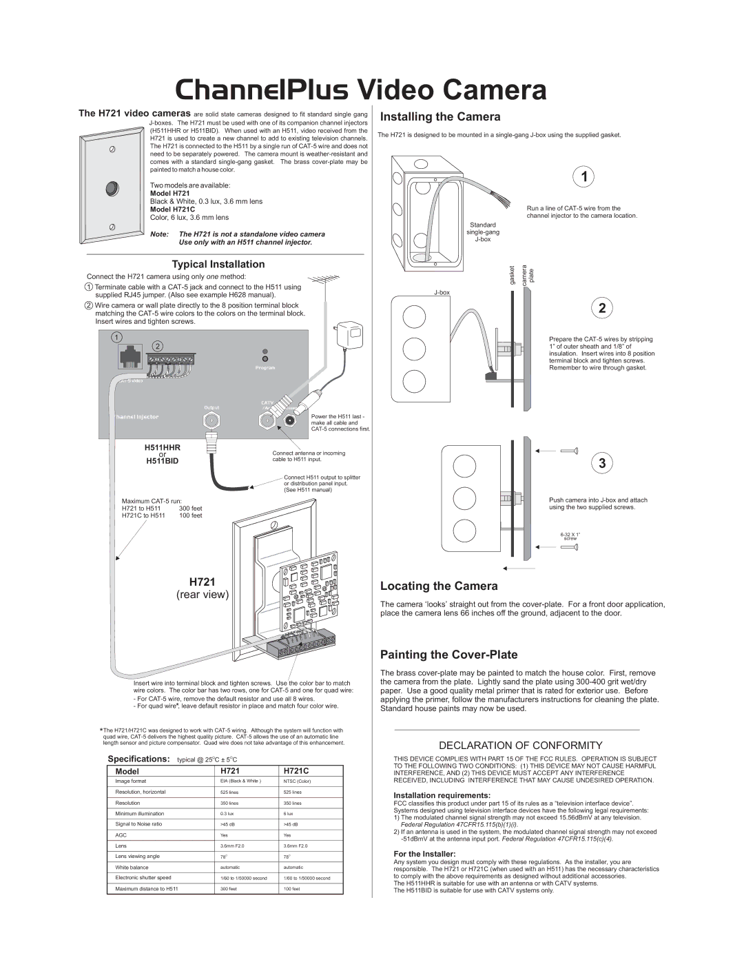
Installing the Camera
The H721 is designed to be mounted in a
1
Run a line of
Standard
Typical Installation
Connect the H721 camera using only one method:
1Terminate cable with a
2Wire camera or wall plate directly to the 8 position terminal block matching the
1
2
Program
| CATV |
|
Output | /Ant | Power |
Channel Injector |
| Power the H511 last - |
|
| make all cable and |
|
|
gasket | camera plate |
|
2
Prepare the
H511HHR |
| Connect antenna or incoming | |
or |
|
| |
H511BID |
|
| cable to H511 input. |
|
|
| |
|
|
| Connect H511 output to splitter |
|
|
| or distribution panel input. |
|
|
| (See H511 manual) |
Maximum | |||
H721 to H511 | 300 feet | ||
H721C to H511 | 100 feet | ||
H721
(rear view)
Insert wire into terminal block and tighten screws. Use the color bar to match wire colors. The color bar has two rows, one for
-For
-For quad wire*, leave default resistor in place and match four color wire.
*The H721/H721C was designed to work with
3
Push camera into
screw
Locating the Camera
The camera ‘looks’ straight out from the
Painting the Cover-Plate
The brass
DECLARATION OF CONFORMITY
Specifications: typical @ 25OC ± 5OC
Model | H721 |
Image format | EIA (Black & White ) |
Resolution, horizontal | 525 lines |
Resolution | 350 lines |
Minimum illumination | 0.3 lux |
Signal to Noise ratio | >45 dB |
AGC | Yes |
Lens | 3.6mm F2.0 |
Lens viewing angle | 78O |
White balance | automatic |
Electronic shutter speed | 1/60 to 1/50000 second |
Maximum distance to H511 | 300 feet |
|
|
H721C
NTSC (Color)
525lines
350lines
6lux >45 dB Yes 3.6mm F2.0 78O
automatic
1/60 to 1/50000 second
100 feet
THIS DEVICE COMPLIES WITH PART 15 OF THE FCC RULES. OPERATION IS SUBJECT TO THE FOLLOWING TWO CONDITIONS: (1) THIS DEVICE MAY NOT CAUSE HARMFUL INTERFERENCE, AND (2) THIS DEVICE MUST ACCEPT ANY INTERFERENCE RECEIVED, INCLUDING INTERFERENCE THAT MAY CAUSE UNDESIRED OPERATION.
Installation requirements:
FCC classifies this product under part 15 of its rules as a “television interface device”. Systems designed using television interface devices have the following legal requirements:
1)The modulated channel signal strength may not exceed 15.56dBmV at any television. Federal Regulation 47CFR15.115(b)(1)(i).
2)If an antenna is used in the system, the modulated channel signal strength may not exceed
For the Installer:
Any system you design must comply with these regulations. As the installer, you are responsible. The H721 or H721C (when used with an H511) has the necessary characteristics to comply with the above requirements as designed without additional accessories.
The H511HHR is suitable for use with an antenna or with CATV systems. The H511BID is suitable for use with CATV systems only.