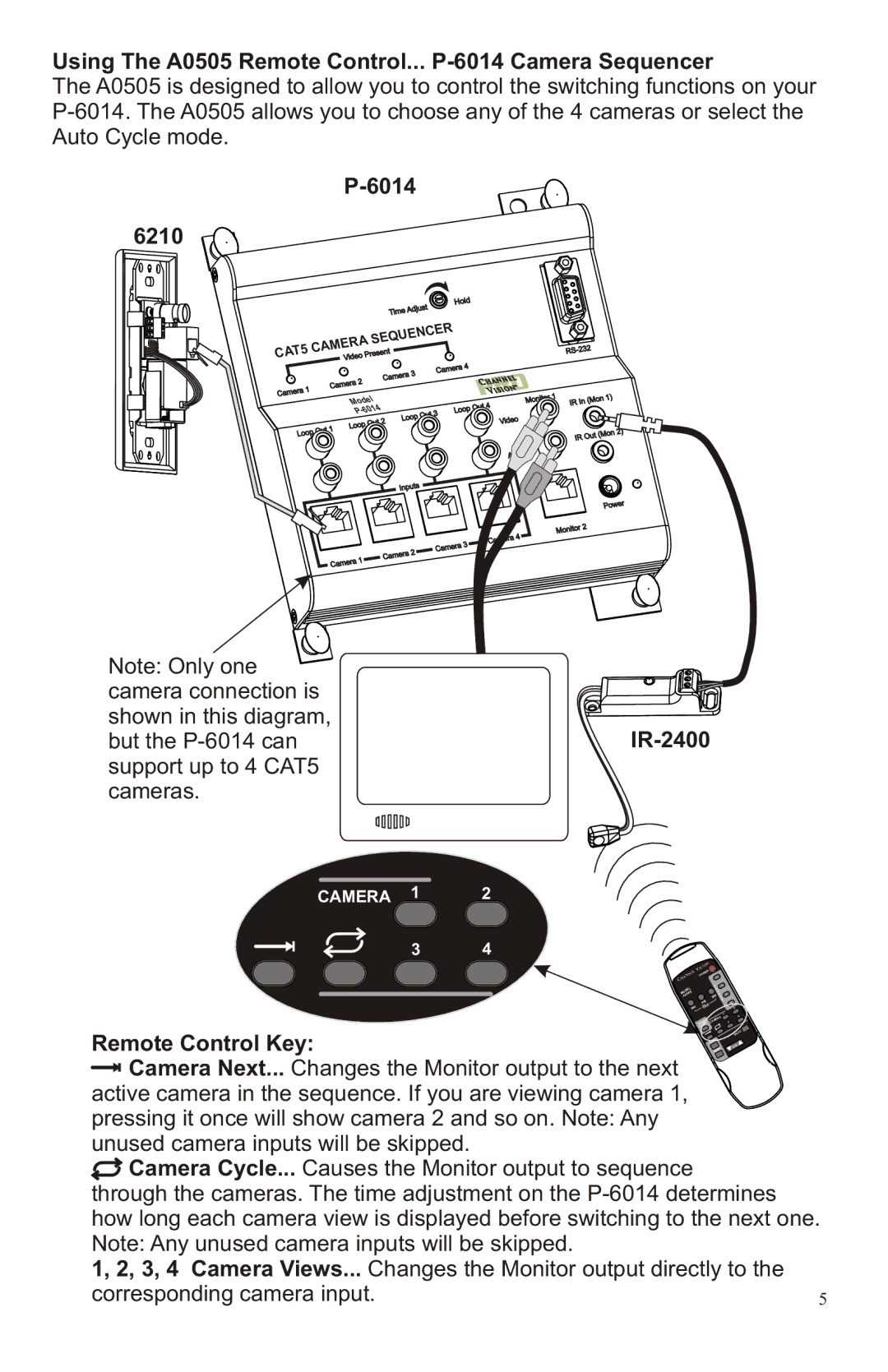
6210, P-6014 specifications
Channel Vision's P-6014 and P-6210 are two of the advanced solutions designed for modern residential and commercial audio/video distribution systems. These products demonstrate a perfect blend of innovative technology, functionality, and ease of use, catering to the needs of both integrators and end-users.The P-6014 is a compact multi-room audio distribution amplifier that can seamlessly connect multiple audio sources to various zones within a home or office. It features a robust power output, allowing up to six independent zones. Each zone can be controlled separately, providing users with the ability to enjoy different audio sources simultaneously. The P-6014 is equipped with advanced DSP (Digital Signal Processing) technology, which ensures high-quality audio reproduction while minimizing distortion and enhancing sound clarity.
On the other hand, the P-6210 is an equally impressive component focused on video distribution. This signal distribution system can handle HDMI signals, making it ideal for high-definition video applications. With support for resolutions up to 1080p, the P-6210 offers crystal-clear image quality. It is compatible with various video formats and can distribute signals to multiple displays without compromising on performance.
One of the standout characteristics of both products is their user-friendly operation. They come with intuitive interfaces that simplify configuration and control through web-based applications or third-party control systems. This connectivity feature facilitates remote management and monitoring, allowing users to adjust settings conveniently from their smartphones or tablets.
Channel Vision has also integrated advanced security protocols into these devices, ensuring the safety of audio and video signals during transmission. Incorporating technologies like HDCP (High-bandwidth Digital Content Protection), they allow users to confidently stream protected content without concerns over signal drops or quality degradation.
In summary, the Channel Vision P-6014 and P-6210 represent the pinnacle of audio and video distribution technology. Their main features, including multi-zone audio control, high-definition video transmission, and user-friendly interfaces, make them ideal choices for anyone looking to enhance their multimedia experience in residential and commercial environments. With a commitment to quality and innovation, Channel Vision continues to be a trusted name in the evolving landscape of audio and video technology.

