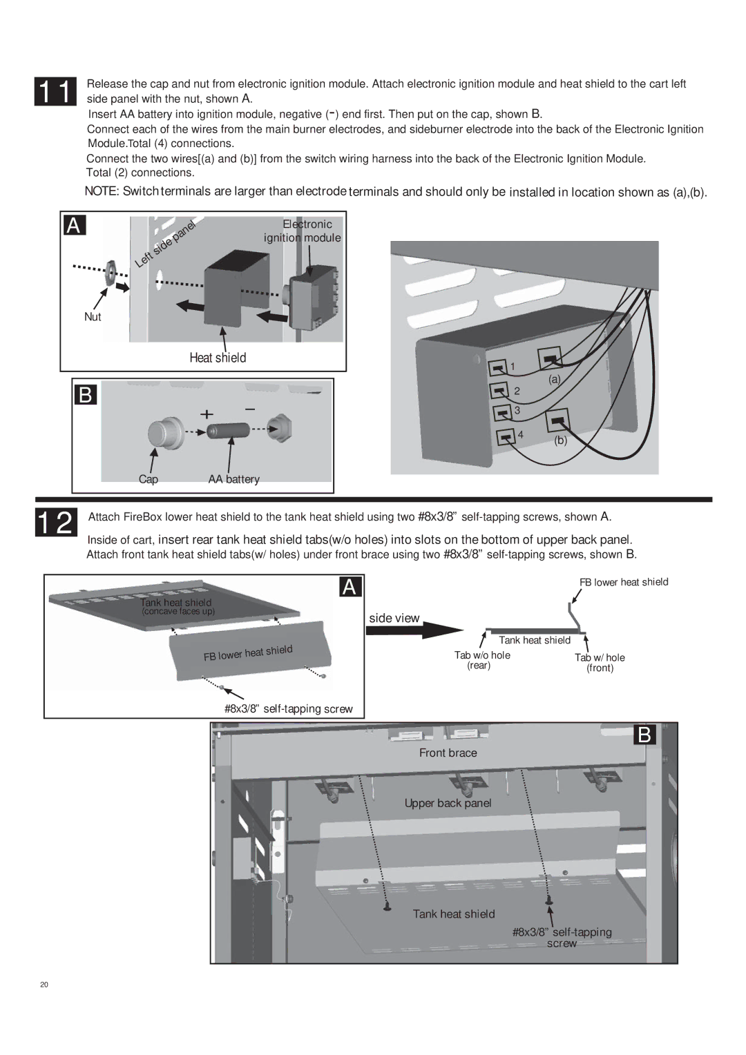
11 Release the cap and nut from electronic ignition module. Attach electronic ignition module and heat shield to the cart left side panel with the nut, shown A.
Insert AA battery into ignition module, negative
Connect each of the wires from the main burner electrodes, and sideburner electrode into the back of the Electronic Ignition Module.Total (4) connections.
Connect the two wires[(a) and (b)] from the switch wiring harness into the back of the Electronic Ignition Module. Total (2) connections.
NOTE: Switch terminals are larger than electrode terminals and should only be installed in location shown as (a),(b).
A
Nut
B
|
| panel | Electronic |
| side | ignition module | |
Left |
|
| |
|
|
|
Heat shield
1
2
(a)
+-
![]() 3
3
4 | (b) |
|
Cap | AA battery |
12
Attach FireBox lower heat shield to the tank heat shield using two #8x3/8”
Inside of cart, insert rear tank heat shield tabs(w/o holes) into slots on the bottom of upper back panel. Attach front tank heat shield tabs(w/ holes) under front brace using two #8x3/8”
A
Tank heat shield (concave faces up)
FB lower | heat shield |
|
#8x3/8”
|
|
| FB lower heat shield | |||
side view |
|
|
|
| ||
|
|
|
|
|
|
|
|
| Tank heat shield |
|
|
|
|
Tab w/o hole | Tab w/ hole | |||||
(rear) |
|
|
| (front) | ||
B
Front brace
Upper back panel
Tank heat shield
#8x3/8”
screw
20