Blanking Plate

Back of the Stove

one return tapping is used. Set the high limit thermostat at 85°C and the low limit thermostat at 45°C. Radiators may be either manually or thermostatically controlled.

CONNECTIONS TO

Soot Door

In Side or Rear Of Chimney

Blanking Plate

Clamping Plate

with fold horizontal


Clamping plate finishes flush with inside face of firebox top and bottom.

Seal Blanking Plate with fire cement

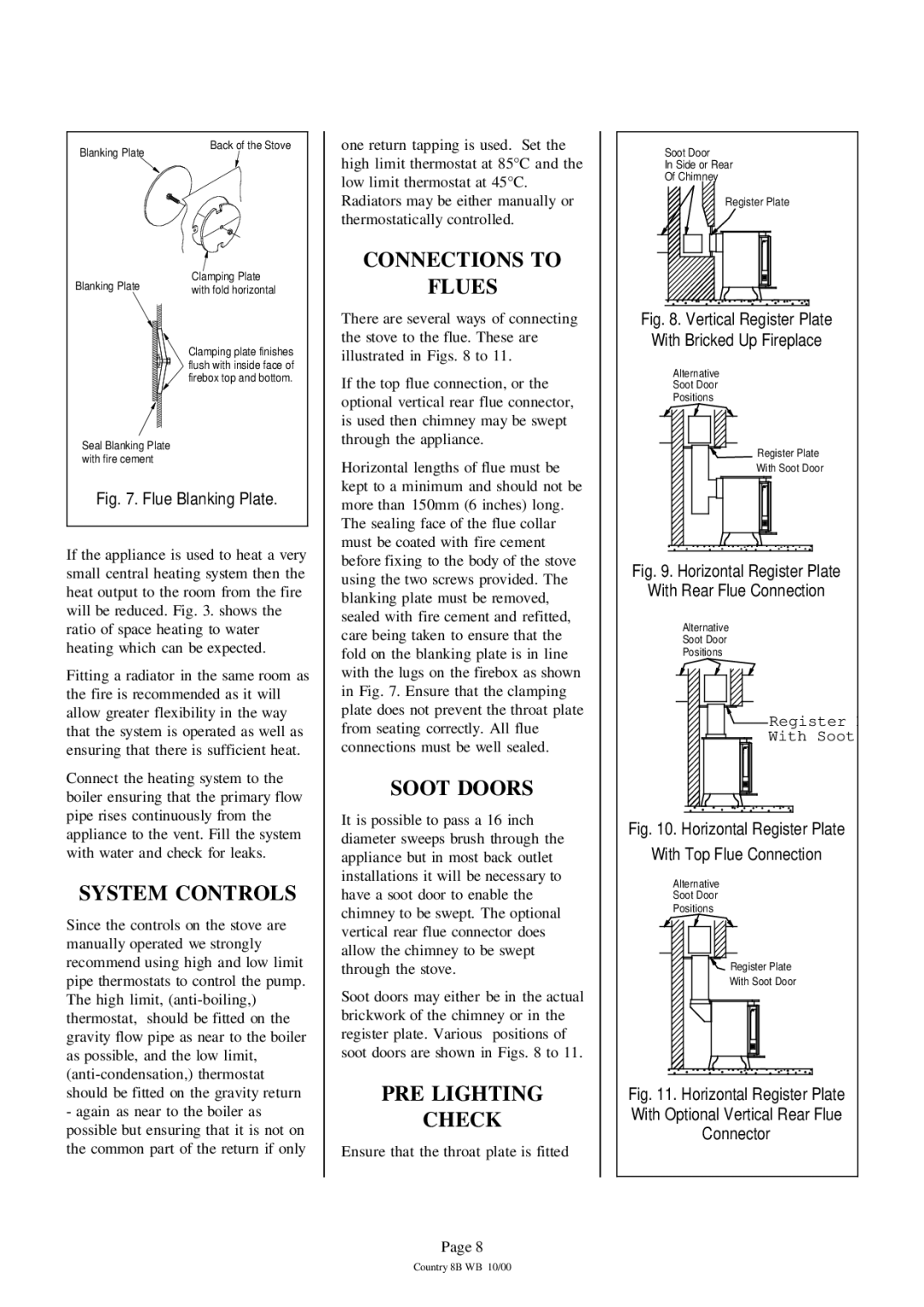
Fig. 7. Flue Blanking Plate.

If the appliance is used to heat a very small central heating system then the heat output to the room from the fire will be reduced. Fig. 3. shows the ratio of space heating to water heating which can be expected.

Fitting a radiator in the same room as the fire is recommended as it will allow greater flexibility in the way that the system is operated as well as ensuring that there is sufficient heat.

Connect the heating system to the boiler ensuring that the primary flow pipe rises continuously from the appliance to the vent. Fill the system with water and check for leaks.

SYSTEM CONTROLS

Since the controls on the stove are manually operated we strongly recommend using high and low limit pipe thermostats to control the pump. The high limit, (anti-boiling,) thermostat, should be fitted on the gravity flow pipe as near to the boiler as possible, and the low limit, (anti-condensation,) thermostat should be fitted on the gravity return

-again as near to the boiler as possible but ensuring that it is not on the common part of the return if only

FLUES

There are several ways of connecting the stove to the flue. These are illustrated in Figs. 8 to 11.

If the top flue connection, or the optional vertical rear flue connector, is used then chimney may be swept through the appliance.

Horizontal lengths of flue must be kept to a minimum and should not be more than 150mm (6 inches) long. The sealing face of the flue collar must be coated with fire cement before fixing to the body of the stove using the two screws provided. The blanking plate must be removed, sealed with fire cement and refitted, care being taken to ensure that the fold on the blanking plate is in line with the lugs on the firebox as shown in Fig. 7. Ensure that the clamping plate does not prevent the throat plate from seating correctly. All flue connections must be well sealed.

SOOT DOORS

It is possible to pass a 16 inch diameter sweeps brush through the appliance but in most back outlet installations it will be necessary to have a soot door to enable the chimney to be swept. The optional vertical rear flue connector does allow the chimney to be swept through the stove.

Soot doors may either be in the actual brickwork of the chimney or in the register plate. Various positions of soot doors are shown in Figs. 8 to 11.

PRE LIGHTING

CHECK

Ensure that the throat plate is fitted

Page 8

Fig. 8. Vertical Register Plate

With Bricked Up Fireplace

Alternative

Soot Door

Positions

Register Plate

With Soot Door

Fig. 9. Horizontal Register Plate

With Rear Flue Connection

Alternative

Soot Door

Positions

Register

With Soot

Fig. 10. Horizontal Register Plate

With Top Flue Connection

Alternative

Soot Door

Positions

Register Plate

With Soot Door

Fig. 11. Horizontal Register Plate

With Optional Vertical Rear Flue

Connector

Country 8B WB 10/00

Page 8
Image 8
Charnwood Country 8B installation instructions Connections to, System Controls, Flues, Soot Doors, PRE Lighting Check

Country 8B specifications

Charnwood Country 8B is a remarkable initiative situated within the scenic and dynamic landscape of Charnwood, a district in Leicestershire, England. This project stands as a striking example of how thoughtful planning and innovative technology can converge to create a sustainable and eco-friendly environment.

One of the main features of Charnwood Country 8B is its commitment to preserving the local natural beauty while promoting community living. The development is characterized by its integration into the surrounding countryside, with designed pathways for walking and cycling that encourage residents to engage with the outdoors. The layout promotes a sense of community, with green spaces, parks, and recreational facilities that foster social interaction among residents.

In terms of technology, Charnwood Country 8B incorporates smart infrastructure to enhance the quality of life for its inhabitants. This includes smart energy solutions such as solar panels and wind turbines that provide renewable energy sources for the community. The buildings in this area have been constructed with energy efficiency in mind, employing advanced insulation techniques and energy-efficient windows to minimize energy consumption.

Another significant characteristic of Charnwood Country 8B is its emphasis on sustainable transportation options. The development promotes the use of electric vehicles, with charging stations strategically placed throughout the community. Public transport links are also prioritized, ensuring residents have access to efficient commuting options without reliance on personal vehicles.

Water management technologies play an essential role in maintaining the sustainability of Charnwood Country 8B. This includes the use of sustainable drainage systems (SuDS) that manage rainwater efficiently, reducing the risk of flooding while enhancing the local ecology.

Charnwood Country 8B brings together innovative technologies and sustainable practices harmoniously, making it a model for future developments. Its focus on community, sustainability, and technological advancements showcases the potential for creating attractive living spaces that respect and enhance the natural environment. This initiative not only serves the needs of today's residents but also considers future generations, ensuring a lasting positive impact on the community and the surrounding ecosystem. The development stands as a testament to progress, environment, and family living, embracing a holistic approach to modern life.