LANTERN ASSEMBLY INSTRUCTIONS
Item numbers 1880 and 1885
WARNING – FAILURE TO FOLLOW THESE SAFETY PRECAUTIONS COULD CREATE A
HAZARDOUS CONDITION.
1.This Chimera Lantern product is intended for use with shielded bulb instruments pointed straight down. Refer to the light manufacturer’s recommendations before operating your particular light in this position.
2.Do not leave the Lantern unattended when the light is on.
3.Use the light’s protective screen or shield at all times.
4.Use in a moderate temperature environment with good ventilation and spacing between multiple units.
5.Open the Lantern’s flaps for additional ventilation as required.
6.Maximum power capacity for these products is 500 watts in the 1880, 20” Lantern model, and 1000 watts in the 1885, 30” Lantern model.
ASSEMBLING THE LANTERN
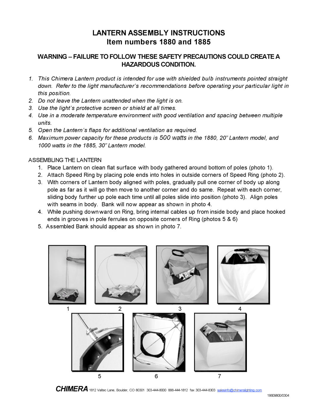
1.Place Lantern on clean flat surface with body gathered around bottom of poles (photo 1).
2.Attach Speed Ring by placing pole ends into holes in outside corners of Speed Ring (photo 2).
3.With corners of Lantern body aligned with poles, gradually pull one corner of body up along pole as far as it will go then move to another corner and do same. Repeat with each corner, sliding body further up pole each time until all poles slide into position (photo 3). Align poles with seams in body. Bank will now appear as shown in photo 4.
4.While pushing downward on Ring, bring internal cables up from inside body and place hooked ends in grooves in pole ferrules on opposite corners of Ring (photos 5 & 6)
5.Assembled Bank should appear as shown in photo 7.
1 | 2 | 3 | 4 | ||
|
|
|
|
|
|
5 | 6 | 7 |
CHIMERA1812 Valtec Lane, Boulder, CO 80301
18609800/0304