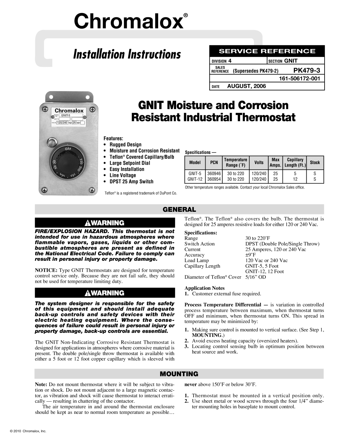
GNIT-5 specifications
The Chromalox GNIT-5 offers a robust solution tailored for industrial heating applications, designed to meet the evolving demands of modern industries. As a part of Chromalox's renowned line of electric heating equipment, the GNIT-5 integrates advanced technology with user-friendly features, ensuring efficiency and reliability.One of the main features of the GNIT-5 is its ability to provide precise temperature control. The integrated digital controller allows for accurate adjustments, promoting optimal heating performance across various processes. This accuracy not only enhances safety by preventing overheating but also contributes to energy savings, making the GNIT-5 an eco-friendly choice for businesses.
The GNIT-5 is equipped with state-of-the-art heating elements that ensure quick and uniform heat distribution. This technology helps minimize hot spots, which can lead to equipment damage or product degradation. The durable construction of the GNIT-5, from high-quality materials to robust insulation, ensures longevity and reliability in challenging industrial environments.
Another notable characteristic of the GNIT-5 is its versatility. It is designed to accommodate a range of applications, including temperature maintenance for pipelines, tank heating, and process heating in various industries such as oil and gas, food processing, and chemical manufacturing. This adaptability makes it an invaluable asset for facilities looking to streamline their heating processes.
Safety is a paramount concern in industrial settings, and the GNIT-5 addresses this with several built-in protective features. These include over-temperature protection and fault indication systems that alert operators to potential issues before they escalate. This proactive approach to safety helps minimize downtime and protects both personnel and equipment.
Ease of installation and maintenance is another advantage of the GNIT-5. Designed with the user in mind, the system features straightforward mounting and wiring processes, reducing the time and effort required for setup. Additionally, maintenance access is facilitated, allowing for regular inspections and servicing to keep the system functioning optimally.
In summary, the Chromalox GNIT-5 stands out in the realm of industrial heating solutions. Its precise temperature control, innovative heating technologies, versatility in application, robust safety features, and user-friendly design make it a top choice for businesses seeking efficient and reliable heat management solutions. As industries continue to evolve, the GNIT-5 remains a key player in ensuring quality and performance.