INSTALLATION (cont’d.)

FIGURE 2

1.Remove back from the indicating label and place over the hole- made in step 1B on the previous page, the word "winter" needs to face towards the louvers.

2.Install the barrier over the threads of the switch and insert the 1/2" hole from inside the terminal box. Secure switch in place with the nut provided.

3.Wire switch into heater wiring (See Diagram 1).

4.Inspect wiring for loose connections and make sure it matches Diagram 1 after wiring.

5.Close cover and reattach screws.

WINTER/SUMMER

BARRIER

MOTOR RELAY

INDICATING LABEL


NUT


Figure 2


SWITCH WITH FACTORY


INSTALLED LEADWIRES

WIRING

1.The element wiring is not affected by addition of the fan only switch/ motor relay and therefore not shown. The after wiring dia- gram supplements the wiring diagram mounted on the inside of the terminal box cover.

2.Disconnect the red wire from the heater contact coil, cut off termi- nal and strip back insulation 3/8”.

3.Disconnect wire from coil of heater contactor from “C3” post of control circuit terminal block.

4.Connect loose wire provided with kit to terminal “A2” of motor relay.

5.Using wire nut, connect the wires modified in steps 2, 3 and 4 together.

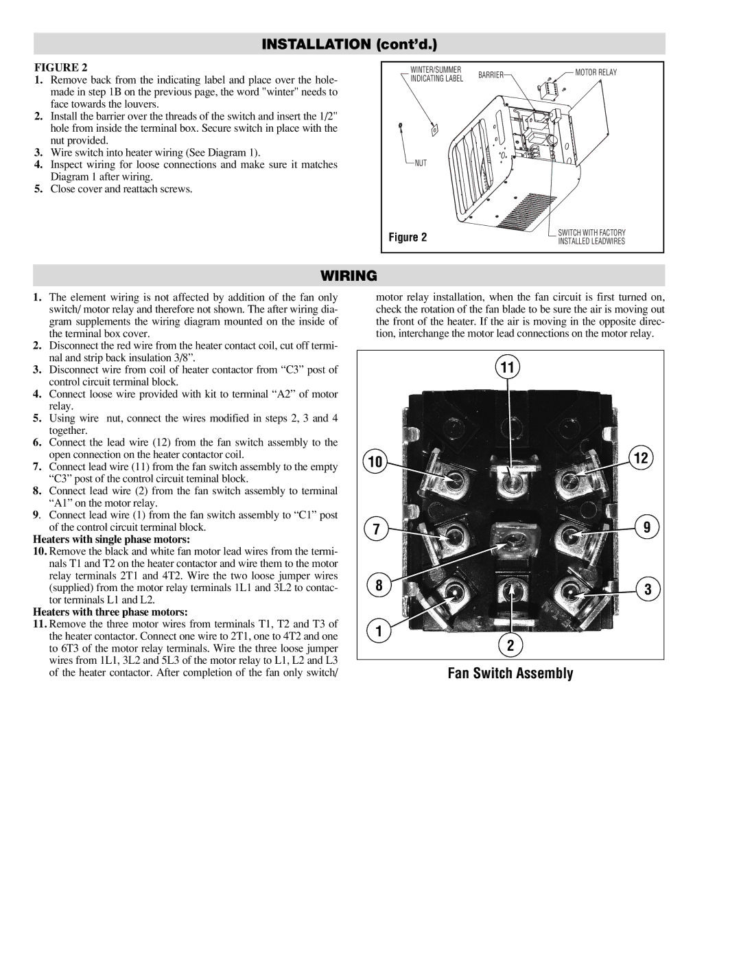
6.Connect the lead wire (12) from the fan switch assembly to the open connection on the heater contactor coil.

7.Connect lead wire (11) from the fan switch assembly to the empty “C3” post of the control circuit teminal block.

8.Connect lead wire (2) from the fan switch assembly to terminal

“A1” on the motor relay.

9. Connect lead wire (1) from the fan switch assembly to “C1” post of the control circuit terminal block.

Heaters with single phase motors:

10.Remove the black and white fan motor lead wires from the termi- nals T1 and T2 on the heater contactor and wire them to the motor

relay terminals 2T1 and 4T2. Wire the two loose jumper wires (supplied) from the motor relay terminals 1L1 and 3L2 to contac- tor terminals L1 and L2.

Heaters with three phase motors:

11.Remove the three motor wires from terminals T1, T2 and T3 of the heater contactor. Connect one wire to 2T1, one to 4T2 and one to 6T3 of the motor relay terminals. Wire the three loose jumper wires from 1L1, 3L2 and 5L3 of the motor relay to L1, L2 and L3 of the heater contactor. After completion of the fan only switch/

motor relay installation, when the fan circuit is first turned on, check the rotation of the fan blade to be sure the air is moving out the front of the heater. If the air is moving in the opposite direc- tion, interchange the motor lead connections on the motor relay.

11

10

12

7

9

8

3

1

2

Fan Switch Assembly

Page 2
Image 2
Chromalox HVS-03, HVS-02 installation instructions Installation cont’d, Wiring, Fan Switch Assembly

HVS-02, HVS-03 specifications

Chromalox is a renowned leader in thermal technology solutions, providing a wide range of heating and temperature control products designed to meet diverse industrial needs. Among their notable offerings are the HVS-03 and HVS-02 models, which exemplify the company's commitment to innovation, efficiency, and reliability in thermal management.

The Chromalox HVS-03 is engineered for high-performance requirements and stands out with its advanced heating technology. This model features a robust and compact design, making it suitable for various applications, including process heating, fluid heating, and even some specialized laboratory uses. One of the key characteristics of the HVS-03 is its precise temperature control system. This system utilizes advanced sensors and controllers that ensure accuracy, allowing users to maintain optimal thermal conditions, thus improving operational efficiency and reducing waste.

On the other hand, the HVS-02 model provides a versatile solution for environments that require consistent heating at lower power capacities. This model is designed for easier installation and flexibility, making it an excellent choice for smaller operations or batch processes. Like the HVS-03, it incorporates user-friendly controls that enhance the ease of operation, enabling staff to quickly adjust settings as needed to accommodate varying thermal loads.

Both models feature durable construction materials that ensure longevity even in harsh industrial environments. They are equipped with advanced insulation technology that reduces energy loss, making them energy-efficient options compared to traditional heating systems. Additionally, the HVS models are designed with safety features, including over-temperature protection and fail-safe mechanisms, providing peace of mind for operators.

In terms of technology, the HVS series integrates smart heating capabilities that allow for remote monitoring and control. This connectivity not only streamlines operations but also aids in predictive maintenance, minimizing downtime and extending the lifespan of the equipment.

Overall, the Chromalox HVS-03 and HVS-02 are outstanding thermal solutions capable of meeting the varying demands of industrial heating applications. Their state-of-the-art technology, user-friendly features, and robust design make them the preferred choice for professionals seeking efficient, reliable, and versatile thermal management systems. By choosing Chromalox, users benefit from a legacy of quality and innovation that enhances productivity and operational effectiveness in any setting.