WIRING

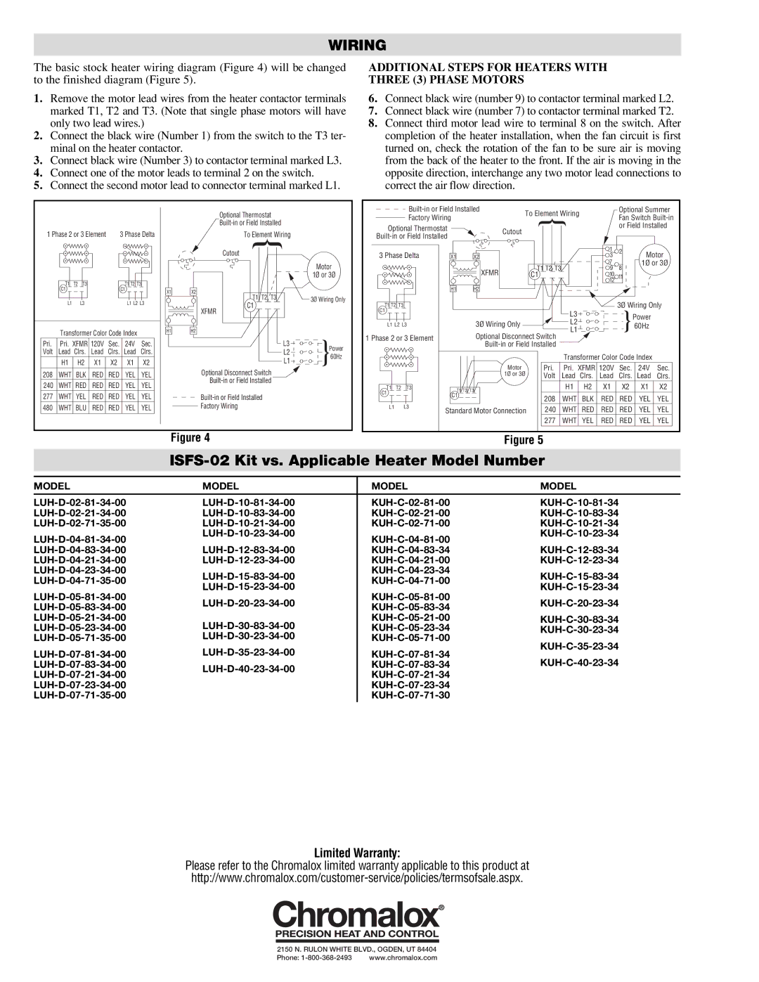
The basic stock heater wiring diagram (Figure 4) will be changed to the finished diagram (Figure 5).

1.Remove the motor lead wires from the heater contactor terminals marked T1, T2 and T3. (Note that single phase motors will have only two lead wires.)

2.Connect the black wire (Number 1) from the switch to the T3 ter- minal on the heater contactor.

3.Connect black wire (Number 3) to contactor terminal marked L3.

4.Connect one of the motor leads to terminal 2 on the switch.

5.Connect the second motor lead to connector terminal marked L1.

ADDITIONAL STEPS FOR HEATERS WITH THREE (3) PHASE MOTORS

6.Connect black wire (number 9) to contactor terminal marked L2.

7.Connect black wire (number 7) to contactor terminal marked T2.

8.Connect third motor lead wire to terminal 8 on the switch. After completion of the heater installation, when the fan circuit is first turned on, check the rotation of the fan to be sure air is moving from the back of the heater to the front. If the air is moving in the opposite direction, interchange any two motor lead connections to correct the air flow direction.

1 Phase 2 or 3 Element

3 Phase Delta

Optional Thermostat Built-in or Field Installed

To Element Wiring

Built-in or Field Installed

To Element Wiring

Optional Summer

Factory Wiring

Fan Switch Built-in


Optional Thermostat

Cutout

or Field Installed


Built-in or Field Installed


1


T1


T2


T3


T1

T2

T3


C1


C1


L1


L3


L1 L2 L3


Transformer Color Code Index


Pri.

Pri. XFMR 120V

Sec.


24V

Sec.


Volt

Lead

Clrs.

Lead

Clrs.


Lead

Clrs.


H1

H2


X1

X2


X1

X2


X1

H1

Cutout

X2

XFMR

H2


Motor


1Ø or 3Ø

T1

T2

T3


3Ø Wiring Only

C1


L3

Power


L2


60Hz


L1


3 Phase Delta

X1

X2


3

2

Motor


T1 T2 T3

7

8

1Ø or 3Ø


XFMR

9


C1

10

11


12


H1

H2


T1 T2 T3


3Ø Wiring Only

C1


L3


Power


L1 L2 L3


3Ø Wiring Only


L2


60Hz


L1


1 Phase 2 or 3 Element


Optional Disconnect Switch


Built-in or Field Installed


Transformer Color Code Index

208

WHT BLK RED RED YEL

YEL

240

WHT

RED

RED

RED

YEL

YEL

277

WHT

YEL

RED

RED

YEL

YEL

480

WHT

BLU

RED

RED

YEL

YEL

Optional Disconnect Switch Built-in or Field Installed

Built-in or Field Installed

Factory Wiring


Motor

Pri.

Pri.

XFMR 120V

Sec.

24V

Sec.


1Ø or 3Ø

Volt

Lead

Clrs.

Lead

Clrs.

Lead

Clrs.


H1

H2

X1

X2

X1

X2

T1


T2


T3


T1 T2 T3


C1


C1


208

WHT

BLK

RED

RED

YEL

YEL


L1


L3


Standard Motor Connection

240

WHT

RED

RED

RED

YEL

YEL


277

WHT

YEL

RED

RED

YEL

YEL

Figure 4

Figure 5

ISFS-02 Kit vs. Applicable Heater Model Number

MODEL

MODEL

MODEL

MODEL


LUH-D-02-81-34-00

LUH-D-10-81-34-00

KUH-C-02-81-00

KUH-C-10-81-34

LUH-D-02-21-34-00

LUH-D-10-83-34-00

KUH-C-02-21-00

KUH-C-10-83-34

LUH-D-02-71-35-00

LUH-D-10-21-34-00

KUH-C-02-71-00

KUH-C-10-21-34

LUH-D-04-81-34-00

LUH-D-10-23-34-00

KUH-C-04-81-00

KUH-C-10-23-34


LUH-D-04-83-34-00

LUH-D-12-83-34-00

KUH-C-04-83-34

KUH-C-12-83-34

LUH-D-04-21-34-00

LUH-D-12-23-34-00

KUH-C-04-21-00

KUH-C-12-23-34

LUH-D-04-23-34-00

LUH-D-15-83-34-00

KUH-C-04-23-34

KUH-C-15-83-34

LUH-D-04-71-35-00

KUH-C-04-71-00

LUH-D-15-23-34-00

KUH-C-15-23-34

LUH-D-05-81-34-00

KUH-C-05-81-00

LUH-D-20-23-34-00

KUH-C-20-23-34

LUH-D-05-83-34-00

KUH-C-05-83-34


LUH-D-05-21-34-00

LUH-D-30-83-34-00

KUH-C-05-21-00

KUH-C-30-83-34

LUH-D-05-23-34-00

KUH-C-05-23-34

KUH-C-30-23-34

LUH-D-05-71-35-00

LUH-D-30-23-34-00

KUH-C-05-71-00

KUH-C-35-23-34

LUH-D-07-81-34-00

LUH-D-35-23-34-00

KUH-C-07-81-34

KUH-C-40-23-34

LUH-D-07-83-34-00

LUH-D-40-23-34-00

KUH-C-07-83-34

LUH-D-07-21-34-00

KUH-C-07-21-34


LUH-D-07-23-34-00


KUH-C-07-23-34


LUH-D-07-71-35-00


KUH-C-07-71-30


Limited Warranty:

Please refer to the Chromalox limited warranty applicable to this product at

http://www.chromalox.com/customer-service/policies/termsofsale.aspx.

2150 N. RULON WHITE BLVD., OGDEN, UT 84404

Phone: 1-800-368-2493

www.chromalox.com

Page 2
Image 2
Chromalox ISFS-02 installation instructions Wiring, Additional Steps for Heaters with Three 3 Phase Motors

ISFS-02 specifications

The Chromalox ISFS-02 is a robust and versatile industrial heating solution designed to meet the demands of various applications in the manufacturing and processing industries. Known for its reliability and efficiency, the ISFS-02 is a crucial component in operations that require precise temperature control and consistent heat delivery.

One of the main features of the ISFS-02 is its advanced control technology, which allows for seamless integration into existing systems. The device is equipped with a state-of-the-art digital controller that offers extensive programming options. This enables users to customize temperature profiles, ensuring that specific heating requirements are met with precision. Additionally, the controller features a user-friendly interface for effortless operation and monitoring.

The Chromalox ISFS-02 employs a unique modular design, allowing for easy installation and maintenance. This design not only reduces downtime but also enables scalability, letting users add heating elements as their operational requirements evolve. This flexibility is particularly beneficial in industries where production needs can change rapidly.

Energy efficiency is another hallmark of the ISFS-02. By incorporating advanced heating technology, the device minimizes energy consumption while maximizing heat output. This feature is especially important in today's environmentally conscious climate, where reducing energy costs and carbon footprints is a priority for many businesses.

Moreover, the ISFS-02 is built to withstand harsh industrial environments. Its durable construction, combined with high-quality materials, ensures reliable performance under extreme conditions. This robustness significantly extends the lifespan of the heating system, making it a long-term investment for organizations.

In terms of safety, the ISFS-02 incorporates multiple protective features, including over-temperature protection and fault monitoring systems. These features provide peace of mind, knowing that the system can operate safely without risk of overheating or equipment failure.

Additionally, the ISFS-02 supports various heating applications, from process heating to freeze protection. Its adaptability makes it suitable for multiple sectors, including food processing, chemical manufacturing, and pharmaceuticals.

In summary, the Chromalox ISFS-02 stands out as a premium industrial heating solution characterized by its advanced control technology, modular design, energy efficiency, durable construction, and safety features. Its ability to cater to a range of applications makes it an essential investment for businesses seeking reliable and efficient heating solutions.